Do it this way.
Set your signal generator to where your meter reads 25kHz.
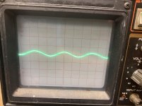
Set your scope the same as when you posted the waveform. Post image of the scope display on your signal generator.
Set your signal generator to where your meter reads 25kHz.
Set your scope the same as when you posted the waveform. Post image of the scope display on your signal generator.
Is the variable pot on your timebase set to cal?
Rotate the timebase from one end of its range to the other. On both ends, does it align with the last mark.
Rotate the timebase from one end of its range to the other. On both ends, does it align with the last mark.
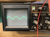
OK. Try this. Power up another amp and see how many cycles are displayed across the display on 5us.
How much current is it drawing with the FETs in the circuit?
Did you load every FET location?
How much current is it drawing with the FETs in the circuit?
Did you load every FET location?
I loaded all fets then I removed the fets and only used 1 in each bank .
Amp draws 40 amps of current .
And I can get the scope to display more cycles if needed
Amp draws 40 amps of current .
And I can get the scope to display more cycles if needed
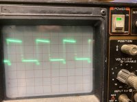
The problem is that the scope will typically display 3 cycles when the scope is set to 10us. On 5us, it should display half of that. You're showing 5 cycles on 5us. If that's accurate, the problem could be the frequency.
Did you run the timebase from end to end to confirm that it was able to reach the markings on each end of travel?
That's significantly lower than the amp you were working on but the other may not be extreme enough to cause 40 amps of current draw. It's still looking like a shorted transformer.
Can you get a frequency reading on this amp?
That's significantly lower than the amp you were working on but the other may not be extreme enough to cause 40 amps of current draw. It's still looking like a shorted transformer.
Can you get a frequency reading on this amp?
That's about double what I'd expect. The meter may have a poor quality filter or trigger circuit.
Connect a 0.001uf cap across the probes and try again.
Connect a 0.001uf cap across the probes and try again.
I noticed with a current limiter in line the amp will not draw excessive current.
It will idle around 1 amp of current draw
If I remove the current limiter it draws excessive current instantly
It will idle around 1 amp of current draw
If I remove the current limiter it draws excessive current instantly
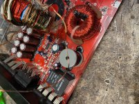
If the area of damaged enamel is just a point where two windings were rubbing, you can insert any type of insulator. The location determines what will work. If the winding overheated over a length, you have to replace the winding, generally. Without more detailed information and a clearly focused image, it's hard to be more specific.
- Home
- General Interest
- Car Audio
- Sundown SAE-1000D