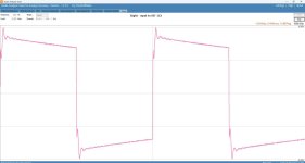
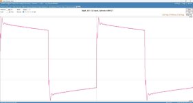
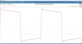
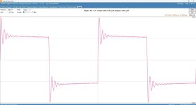
That won't change the severe overshoot. Make sure your test equipment is not the problem.
Are you certain it is not in the preamp?
Are you certain it is not in the preamp?
The equipment works fine with other amps so I don't think it's the problem.
I am not sure if it's the preamp section. I need to buy another 12ax7 to test first since the plate voltage of the left and right of 12ax7 have 7v different. B+ is the same on both sides.
I am not sure if it's the preamp section. I need to buy another 12ax7 to test first since the plate voltage of the left and right of 12ax7 have 7v different. B+ is the same on both sides.
Alashikata,
Amazing. The schematic in post # 1 shows a 6SN7.
It does not show the 12AX7 you mentioned.
If you changed the socket from an 8 pin octal, to a 9 pin noval, and changed from a 6SN7 to a 12AX7, the circuit will not work properly.
And, it will give very short life to the 12AX7.
Did you mean a 12AX7 separate preamp that is feeding the square wave to the power amplifier.
Do not test a preamp and power amplifier at the same time, unless you have checked each one separately first.
Last edited:
6A3sUMMER
Sorry for confusing, that schematic was from dwjames's amp, I have similar problem as his. I have different 300B PP with 12ax7.
Sorry for confusing, that schematic was from dwjames's amp, I have similar problem as his. I have different 300B PP with 12ax7.
Alishikata,
If you can, please post a complete and accurate schematic of your 12AX7 300B PP amplifier.
If you can, please post a complete and accurate schematic of your 12AX7 300B PP amplifier.
It isn't an instability, not a misadjusted probe, but maybe extreme crosstalk in the preamp.
Can you test the amp one channel at a time to rule that out?
Can you test the amp one channel at a time to rule that out?
If you have an amplifier that has strange waveform(s) on 100Hz, 1k, and 10k square waves, (with a non-inductive load resistor) . . .
Just wait until you see what the waveforms look like with a loudspeaker connected.
Caution: Do this testing at very low power levels, or you may burn out your tweeter, and destroy your ears too.
Just wait until you see what the waveforms look like with a loudspeaker connected.
Caution: Do this testing at very low power levels, or you may burn out your tweeter, and destroy your ears too.
Alishikata,
You said: "mine is 16w but 10w has 2% distortion."
Testing a power amplifier into a proper load resistor is one thing.
But then connecting a loudspeaker instead of a load resistor may cause intermodulation distortion, harmonic distortion, and clipping.
Suppose an 8 Ohm loudspeaker has impedance versus frequency of from 4 Ohms to 25 Ohms.
At 4 Ohms, the amplifier may run out of current, so it clips.
At 25 Ohms, the amplifier gain may increase, it may run out of voltage, so it clips.
10 Watts into 8 Ohms is 1.12 Amps
10 Watts into 4 Ohms is 1.58 Amps
10 Watts into 8 Ohms is 8.94 Volts
10 Watts into 25 Ohms is 15.8 Volts
Plus, even without clipping, distortion levels change because of the loudspeaker's elliptical impedance at many frequencies (elliptical load shape; instead of a flat load line).
Last edited:
6A3sUMMER
I have posted this before and the schematic was from post #18 of Jazbo8 https://www.diyaudio.com/community/...-for-this-300b-to-improve.335586/post-5737557
When I got this amp as used for around 200 bucks, the whole thing was messed up. B+ was 320v and hum on speakers. Finally, it took a while to rewire everything but didn't get the voltage as the schematic B1+ =389v, B2+: 309v, and B3+130v, no more hum on speakers. The sound is great, didn't seem any problem. I didn't have the analyzer equipment until recently so I did the test to see what it shows. It's a 300B PP so total is 16w where the distortion around 10% at 16w (graph on post #18 page 1)
The sound is great, didn't seem any problem. I didn't have the analyzer equipment until recently so I did the test to see what it shows.
It's very important to fix this extreme problem. Is it in both monoblocks?
Depanatoru,
Thanks for linking your schematic!
rayma,
Yes, the problem needs to be fixed.
I see global negative feedback around 3 stages, with a compensation cap across the negative feedback resistor, a dominant frequency pole on the input tube's plate, and whatever output transformer that is being employed.
It is a good, standard, well known circuit topology.
(Fortunately, it is not a Williamson circuit (Williamson circuits have the additional need for low frequency compensation).
Perhaps the output transformer is not the same as the one used by the original circuit when the compensation was adjusted.
If the output transformer is not the same model as the original, I am not surprised that there is an overshoot, but that could perhaps be reduced by changing the compensation.
Depanatoru,
Hopefully you will be able to reduce the spike.
Have Fun!
Last edited:
rayma
I am thinking to build another amp while trying to fix without additional cost so I haven't decided if I want to replace the PT. I have been using the KT88 more often until I got back to this amp couple days ago. It's not monoblocks. B+ rail go to left and right. So far the B1 and and B2 are the same except B3 has 7v different 123v and 130v
6A3sUMMER
Is there any range that you would recommend? Like 12k to 33k and 220-470pf cap?
Alishikata,
I have to admit, I have never adjusted a 3 stage amplifier's global negative feedback loop.
Perhaps someone else will help you with the compensation:
Is Post # 30 the complete and accurate schematic?
Then list the exact model of the output transformer you will be using.
I have to admit, I have never adjusted a 3 stage amplifier's global negative feedback loop.
Perhaps someone else will help you with the compensation:
Is Post # 30 the complete and accurate schematic?
Then list the exact model of the output transformer you will be using.
Last edited:
rayma
I am thinking to build another amp while trying to fix without additional cost so I haven't decided if I want to replace the PT. I have been using the KT88 more often until I got back to this amp couple days ago. It's not monoblocks. B+ rail go to left and right.
No immediate reason to replace the transformer, but there's a very good reason to fix the overshoot.
Since this is a stereo amp, it could be crosstalk. Test only one channel at a time.
Post photos of the construction and area around the input sockets.
6A3sUMMER amd rayma
Thank you and appreciate for helping, I have checked all the resistors that match with the schematic. However, as you know the chinese amp never list any specs of OPT and PT. I was able to figure out the PT voltage but not OPT. I will get some resistors and caps to play around with 1 channel at a time. Then report back later.
Thank you and appreciate for helping, I have checked all the resistors that match with the schematic. However, as you know the chinese amp never list any specs of OPT and PT. I was able to figure out the PT voltage but not OPT. I will get some resistors and caps to play around with 1 channel at a time. Then report back later.
While I wait for the Non-inductive load resistor, I did a few more tests with the regular cheapo 8ohm dummy load to see how far back the signal was overshooting like this.
It's definitely present on the output of the phase splitter interstage transformer / grid of the 300Bs 👍

so I checked the input of that transformer / output from the 6SN7

there's definitely a weird glitch there, possibly a result of the 2 halves of the 6SN7 joined in parallel and having slightly differing outputs?
I'm using PSvane cv181-t mkii 6SN7 tubes, so I also checked some other Sylvania ones I have here to compare and it's very similar

plus a check of the input to the 6SN7 just to be sure my test gear isn't introducing issues

I tested with a grid 6.8kohm grid stopper resistor between the pot and the 6SN7 input and it changed the 6SN7 output shape slightly

but not the output from the phase splitter, which looked same as before.

I'd be interested to test a snubber across the secondary of the phase splitter, but I also definitely don't want to run the risk of interfering with the high frequency content of my musical signal. Could anyone suggest some starting values for a snubber which would err on the side of caution?
As you say though, I'm potentially chasing a problem here which doesn't exist under normal circumstances or doesn't cause any real issue in the audio realm, so maybe I should use my energies elsewhere....
I bet you will see the "ring" on both of the 300B grids. They are both at ground (0 Volts DC).
Scope probe tips can easily and safely connect there, check the waveform.
It's definitely present on the output of the phase splitter interstage transformer / grid of the 300Bs 👍
so I checked the input of that transformer / output from the 6SN7

there's definitely a weird glitch there, possibly a result of the 2 halves of the 6SN7 joined in parallel and having slightly differing outputs?
I'm using PSvane cv181-t mkii 6SN7 tubes, so I also checked some other Sylvania ones I have here to compare and it's very similar

plus a check of the input to the 6SN7 just to be sure my test gear isn't introducing issues

One simple fix you can try is a 5K or 10K grid stopper on the 6SN7, between the pot and the grid. That might be enough to reduce the ringing a fair amount.
I tested with a grid 6.8kohm grid stopper resistor between the pot and the 6SN7 input and it changed the 6SN7 output shape slightly

but not the output from the phase splitter, which looked same as before.

I'd be interested to test a snubber across the secondary of the phase splitter, but I also definitely don't want to run the risk of interfering with the high frequency content of my musical signal. Could anyone suggest some starting values for a snubber which would err on the side of caution?
As you say though, I'm potentially chasing a problem here which doesn't exist under normal circumstances or doesn't cause any real issue in the audio realm, so maybe I should use my energies elsewhere....
The last picture shows about 33kHz anomalies (most of IT has more or less bump at high frequency).
First of all try to degrade Q of the IT secondary with resistors (paralleled with 100k resistors for example 100k or 50k or 33k).
The ringing value will decrease (but the "gain" of first stage too).
BTW the correct calculation of RC snubber:
https://www.ti.com/document-viewer/lit/html/SSZTBC7
First of all try to degrade Q of the IT secondary with resistors (paralleled with 100k resistors for example 100k or 50k or 33k).
The ringing value will decrease (but the "gain" of first stage too).
BTW the correct calculation of RC snubber:
https://www.ti.com/document-viewer/lit/html/SSZTBC7
You do realize you are intentionally trying to further reduce the bandwidth (frequency response) of the amp because you don't like the look of a square wave (which you will not find in music)?
Leave it alone or at least test it with sine waves, IMD, distortion, etc. Square wave testing is quite irrelevant, especially with no-feedback designs.
Leave it alone or at least test it with sine waves, IMD, distortion, etc. Square wave testing is quite irrelevant, especially with no-feedback designs.
- Home
- Amplifiers
- Tubes / Valves
- Sun Audio SV-300B PP - Overshoot on square wave test