Hi all, I'm looking to tweak my Sun Audio monoblock amps a little (just some cap and resistor changes and maybe a separate filament transformer) and I thought I'd start with some baseline tests before I change stuff.
I have an Analog Discovery 2 and using the excellent and free Audio Analyzer Suite I'm running a few tests. Generally the distortion is very low and the THD vs Power report shows I get a clean less than 0.5% distortion up to 8W before they max out.
But the basic Square wave scope test shows some pretty wild overshooting. This test is with a 1000hz 0.2vrms Square wave to the input phono and measuring with the probe at the GND and 8ohm speaker terminals with an 8ohm dummy load across it.

Both the left and right amps are identical in their measurement and this overshoot characteristic.
Do you think this is a cause for concern or just a very simple amplifier circuit responding to an unusual test?
Is there anything simple I can do to improve this?
The amps are 300B push-pull with no negative feedback. Here's the circuit

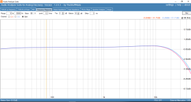
Just for reference, here's the sine wave test

the distortion vs frequency

and the distortion vs power (not quite the advertised 20W max, but 8 clean watts is plenty for me.)

I have an Analog Discovery 2 and using the excellent and free Audio Analyzer Suite I'm running a few tests. Generally the distortion is very low and the THD vs Power report shows I get a clean less than 0.5% distortion up to 8W before they max out.
But the basic Square wave scope test shows some pretty wild overshooting. This test is with a 1000hz 0.2vrms Square wave to the input phono and measuring with the probe at the GND and 8ohm speaker terminals with an 8ohm dummy load across it.
Both the left and right amps are identical in their measurement and this overshoot characteristic.
Do you think this is a cause for concern or just a very simple amplifier circuit responding to an unusual test?
Is there anything simple I can do to improve this?
The amps are 300B push-pull with no negative feedback. Here's the circuit
Just for reference, here's the sine wave test
the distortion vs frequency
and the distortion vs power (not quite the advertised 20W max, but 8 clean watts is plenty for me.)
here's a 1vrms input signal
500hz

1,000hz

2,000hz

I guess that's the same ringing shape/time, but squashed or elongated as the scope adjusts to the signal frequency.
This is all fairly new to me and I'm learning, though I did build and use a Cheapmodo some years ago to make a snubber for a power transformer and this feels like the same sort of issue with possibly a similar fix?
500hz
1,000hz
2,000hz
I guess that's the same ringing shape/time, but squashed or elongated as the scope adjusts to the signal frequency.
This is all fairly new to me and I'm learning, though I did build and use a Cheapmodo some years ago to make a snubber for a power transformer and this feels like the same sort of issue with possibly a similar fix?
Probably a suitable snubber would work, on either the OT secondary, or on the driver transformer secondaries.
Thanks. I guess identifying which transformer would be a start. Hopefully it’s the output transformer as the interstage phase splitter one is a bit more complex and involved.
Maybe a daft question, but could using the 8ohm connection on the output transformer and leaving the 16ohm part open and unloaded contribute to the problem?
Maybe a daft question, but could using the 8ohm connection on the output transformer and leaving the 16ohm part open and unloaded contribute to the problem?
Last edited:
No, the OT is intended to work that way.
Just look at one of the output tube grid waveforms, to see if the driver transformer has the peaking.
Just look at one of the output tube grid waveforms, to see if the driver transformer has the peaking.

You are seeing the band-limited behavior of the amp. Keep in mind, a square wave by FFT consists of an infinite number of odd harmonics, up to the 99999999th etc. Your amp is not capable of those extreme high frequencies, hence the peaked waveform you see. A square wave which has been starved of the most extreme frequencies (which is normal and acceptable)
Run a 10 kHz and see what you get - it will look even better. Run a 50 kHz square wave and you will then really start to see the band limiting action. I don't see much of a need to fix anything unless you intentionally want to limit high frequencies. If the amp had global negative feedback the recommendation might go toward limiting those high frequencies that could risk positive feedback given the unintentional phase shift behaviors. But since you have no feedback, leave her be.
Excellent performance in my view...
Zigzagflux is probably on the money, since there's no global feedback the ringing isn't critical. I know very little about transformer coupling but IIRC changing the loading on the interstage secondary might tame some of the ringing. But honestly, by the time you get to a 10kHz square wave that ringing won't look much different from a classic Williamson amplifier. ;-) In that case you had to worry about instability but here you don't. And I also agree that for a PP 300B with no feedback, that's pretty good bandwidth.
One simple fix you can try is a 5K or 10K grid stopper on the 6SN7, between the pot and the grid. That might be enough to reduce the ringing a fair amount.
One simple fix you can try is a 5K or 10K grid stopper on the 6SN7, between the pot and the grid. That might be enough to reduce the ringing a fair amount.
Your screen shot shows approximately 19 "ring" cycles for every 2kHz square wave cycle.
19 X 2kHz = 38kHz "ring".
The square wave test signal does have that 38kHz sine wave "contained in it". That is what a fast rise 2kHz square wave test tone does (by definition).
It is actually more complicated than that, but the phase and frequency response of the amplifier disturbs both the amplitudes and the phases of several of the odd harmonics that are contained in each and every proper square wave; you are seeing the cumulative effect of that.
Normal music is Not square waves; music does not have excessively fast rise times that a square wave test signal does.
I bet you will see the "ring" on both of the 300B grids. They are both at ground (0 Volts DC).
Scope probe tips can easily and safely connect there, check the waveform.
Make sure to connect the scope probe ground clip to the amplifier ground (like the junction of the two 300B self bias resistors and the interstage transformer's Secondary center tap (junction of the secondary windings).
Make sure to connect a non-inductive load resistor across the output transformers secondary, either 8 Ohms from the 8 Ohm tap to Common, OR
16 Ohms from the 16 Ohm tap to Common. Safe for the amplifier, and also reduces any output transformer "ring" from reflecting from the 300B plates back through the Miller Effect Capacitance to the 300B grids . . . from there all the way to the interstage transformers secondary.
If you see the "ring" there, that means the interstage transformer is the source of the "ring". If that is true, then . . .
The 300B tubes and output transformer can only pass the "ring" on to the speaker terminals.
There are no music harmonics from your Red Book CD player above 22.05kHz; So, there are no sine waves to cause that 38kHz "ring".
Nothing to worry about.
Have a nice music listening session tonight, enjoy the music, and then get a good relaxed sleep.
If the amplifier does not sound good to you . . .
Check the rest of your system, the room, recordings, etc. If there is no way to fix the system sound . . .
Then quote me a price for the amplifier and shipping to the US.
Last edited:
Try to measure its on interstage outputs (5, 8) too.here's a 1vrms input signal
500hz
1,000hz
2,000hz
There is few ten Volt peek.
If such behaviour there, probable appropriate series R-C snubber on IT secondary helps.
euro21,
Interstage outputs 5 and 8 ARE the 300B grids.
I am sorry you missed my Post # 11:
"I bet you will see the "ring" on both of the 300B grids. They are both at ground (0 Volts DC).
Scope probe tips can easily and safely connect there, check the waveform.
Make sure to connect the scope probe ground clip to the amplifier ground (like the junction of the two 300B self bias resistors and the interstage transformer's Secondary center tap (junction of the secondary windings).
Make sure to connect a non-inductive load resistor across the output transformers secondary, 8 Ohms from the 8 Ohm tap".
Whenever a Red Book CD player is used to provide the musical signal . . .
The 38kHz "ring" will Not appear from the amplifier output.
If your 1960's Supercharged Studebaker Avanti only goes 169MPH (it did in a sports car magazine), don't modify it to meet the 170MPH Spec.
Leave well enough alone.
Just my Opinions
Last edited:
Maybe could work fine like this because it has no negative feedback ... but it looks pretty nasty and could also interfere sometimes with normal music ( complex waveform ) .
Thanks all, that's some really helpful food for thought 🙏
Thank you for being specific on this point. I was using a cheapo 100W 8ohm wire-wound chassis-mount resistor as my dummy load. You prompted me to do some reading on Non-Inductive ones which included finding this post which contained an example of a scope output from feeding a square wave into a regular inductive resistor to show the effects and this overshooting looks very familiar.

So at this point I want to grab some decent non-inductive resistors and check again, but that might take me a couple of days to get the parts.
Haha, yes and no 🙂 Sure the regular music on daytime radio is a lot more complex, but I love many kinds of music and especially electronic, some of which is very sparse and indeed can literally just be basic waveforms at times 🤓
eg: (this track has a very slow build and has that hand-tuned wonky Buchla vibe which I fully appreciate is not for everyone, but I love it 🙂)
They are sounding pretty damn good and I'm very fond of them 😊
But at times they sound a little 'forced' at higher volumes and I think there are likely a couple of simple things I can do to improve them, so I wanted to get some baseline measurements before any surgery.
Make sure to connect a non-inductive load resistor across the output transformers secondary
Thank you for being specific on this point. I was using a cheapo 100W 8ohm wire-wound chassis-mount resistor as my dummy load. You prompted me to do some reading on Non-Inductive ones which included finding this post which contained an example of a scope output from feeding a square wave into a regular inductive resistor to show the effects and this overshooting looks very familiar.
So at this point I want to grab some decent non-inductive resistors and check again, but that might take me a couple of days to get the parts.
Normal music is Not square waves
Haha, yes and no 🙂 Sure the regular music on daytime radio is a lot more complex, but I love many kinds of music and especially electronic, some of which is very sparse and indeed can literally just be basic waveforms at times 🤓
eg: (this track has a very slow build and has that hand-tuned wonky Buchla vibe which I fully appreciate is not for everyone, but I love it 🙂)
If the amplifier does not sound good to you . . .
Check the rest of your system, the room, recordings, etc. If there is no way to fix the system sound . . .
Then quote me a price for the amplifier and shipping to the US.
They are sounding pretty damn good and I'm very fond of them 😊
But at times they sound a little 'forced' at higher volumes and I think there are likely a couple of simple things I can do to improve them, so I wanted to get some baseline measurements before any surgery.
- The caps are mostly the original electrolytics from 20 years ago, I wanted to see if modern film caps improved things (I have some Kemet C4AQ here)
- 47uf seems a bit large for 5U4G input cap so I suspect the PT charging pulses may be a bit spikey.
- Power Transformer seems overworked (60 deg C on the casing after half an hour) so I plan to take some of the load off and move the 300B 6.3v filament supply to separate transformer
oh wow yeah, those are some huge spikes!Mine got the same too but no problem with other amps
Out of interest, did you have the X10 switch on the probes there? And do you see the same behaviour if your input signal is higher? I can go to 2.3Vrms signal into mine before it distorts, so 0.2Vrms is fairly low
Yeah it's X10, mine is 16w but 10w has 2% distortion. I believe it's the power supply that I may have to rebuild. However, there is no problem with listening as long as i don't go over 10w.
Attachments

Last edited:
I don't think it' 8ohm dummy load. Mine got the same too but no problem with other amps.
You really need to fix that.
rayma,
I plan to replace the PT and adding a choke because it's 110v and no choke that could be a dirty power supply. My outlet is between 118-120v. Hope, it would fix the issue.
I plan to replace the PT and adding a choke because it's 110v and no choke that could be a dirty power supply. My outlet is between 118-120v. Hope, it would fix the issue.
- Home
- Amplifiers
- Tubes / Valves
- Sun Audio SV-300B PP - Overshoot on square wave test