My mind drifts of to this paper: https://jblpro.com/en/site_elements/tech-note-cone-midrange-compression-drivers-cmcdWhat phase plug design are you using for the MCM 55-1870 to reach 1500Hz?
@tom-danley wrote this on FB, thought it was on-topic:
"I have to say that is a good description of what i call a Synergy horn.
I don't think i have heard anyone describe how the drivers couple into a single radiation as clearly as that.
Because they do couple into "one", something like signals in a circuit and not separate radiators where what you get depends on where you are , one can sometimes make a passive crossover that doesn't have the normal phase association or even none as in a single source in time and space with directivity Something maybe like a Tapped filter in reverse although that's a more recent thought.
Boy it's funny I remember your name from the Bass List, those were fun times and honestly posting there on line helped me keep my sanity in some very sucky personal times. My world at work was mostly below 80Hz with Servodrives and above 20KHz with acoustic levitation and that all came to an end.
Here is the history leading to the, the Unity horn.
You know what they say about desperation and invention, well after the shuttle disaster fall out ended Intersonics in the mid 90's, i had to start over in my career and was desperate. This time my primary job was to design actual loudspeakers for commercial sound for guy i used to Jam with (i played bass).
At a Christmas party he teased me about having recently been in the Great Pyramid to measure the acoustics for a movie and said "make speaker out of a pyramid and make the sound sharper" haha very funny big laughs (actually he was a funny guy).
The next day i was fretting about "what the heck am I going to do" and thought about the wise **** remark and then remembered something Don Davis had said at Synaudcon years earlier, about a new style horn and Don Keele's article "What's so sacred about exponential horns" and his new family constant directivity horns.
Don D commented that the "constant directly" was very good, better than multi-cells but the loading at the low end on the driver was poor.
Ok constant directivity would be real good for this.
I had been making bass horns for for the Servodrives at Intersonics for a decent time but right then it dawned on me that the reason for the poor loading on those new horns at the low end of the driver was the expansion rate was too fast to couple effectively.
There is a "high pass" effect with horns impedance transformation based on the rate of expansion. For an exponential horn with a 32Hz target, the expansion can only double every 2 feet, a 1 foot doubling makes a 64Hz horn and so on. At the apex where the hf driver is, the expansion is very rapid and had to be the problem!
I thought "what if i put mid drivers on the sides of the horn where the expansion was slower and suitable for midrange". I made a horn with the drivers on the sides BUT i put them on the inside of the horn which was not good, too much interference with the hf.
Mounted on the outside with "low pass" ports was better and ports in the corners better yet. I did what you did with tape to experiment with location and effect.
It took cutting more plywood in my cramped garage shop than i would like to think and measuring in a loop to put together enough design rules to make a couple boxes for Sound Physics, the TD-1 and a cube shape and apply for a patent. It seemed like Unity was an apt name for what it did. The patent examiner agreed there was nothing that tried to accomplish this.
In the 80's i used to make electrostatic speakers, i liked them but i always ended up wrecking them (smoke) , probably a dozen different trys, including a home brew direct drive tube amp, they just weren't enough unless your real close.
At intersonics my boss Roy knew i had made them and asked me to remove the protection from his quad ESL63's, i took a deep breath and said well ok BUT those annoying spark gaps are protecting the speaker (and within a few months they were dead)
I took these expensive speakers home and saw the construction was different, radiating rings and a delay line to make it radiate as if it were a point some distance behind.
I cut one end of each gap and set down on the floor to listen to these unique speakers i could never afford up close..
I was struck that the origin of the sound "sounded like" it was behind the electrostatic elements and if you moved your head around a bit, the impression stuck. I had never heard anything like that, an illusion but the only thing i could conclude was since i was hearing that, that it had to be a property of how it radiated.
It took me much longer than you to make these work but as they measured more and more like a single source, they reminded me of when i modified Roy's ESL-63's in that there wasn't an obvious point of origin or minimum distance like on a normal speaker AND the weirdest thing it also became harder
to localize the location in depth when your eyes were closed.
Sure you could point at it, but when facing the speaker, as the sound reaching each ear became more and more identical (like it came from a single tiny point in space) and so it became harder and harder to localize how far away it was.
That property i call "spatial identity" tied to a lack of self interference was desirable at work for commercial sound as it was the self interference large arrays produce that limits the effective working distance. When i figured out how to have multiple hf drivers and still make this work, it became possible to cover the far end of a football field from the scoreboard at one end with as few as one box and based on demo's not advertising.
Sounds impossible? Well it is a big speaker, 10 feet tall but one of them is hiding behind the Iowa Hawk-eye on top of the scoreboard .
The interesting thing for me was reducing the speakers depth signature made a big improvement when listening in stereo and that's always been my interest.
I explained some of that part as it applies to a loudspeaker in a video our sales guys are working on to explain the sound from some new speakers. If you reduce the speakers signature enough, they can disappear into the phantom image so your actually unaware of them and one can do this at a significant scale.
Scott, did you happen to measure the three ranges raw without moving the mic or adjusting the delay (so all three raw responses are at the same time reference)? 🙂
Anyway, I hope this rounds out the history of these horns
Tom Danley

New speaker from Beyma: 3FR30V2
Compares favorably with the faital pro 3FE25 which has featured on a number of MEH projects and can reach around 1.27kHz. Compared to the 3FE25 it has a stronger motor, slightly more xmax, slightly wider voice coil, higher Fs and lower Qes. This should make it go a bit higher in frequency....
Compares favorably with the faital pro 3FE25 which has featured on a number of MEH projects and can reach around 1.27kHz. Compared to the 3FE25 it has a stronger motor, slightly more xmax, slightly wider voice coil, higher Fs and lower Qes. This should make it go a bit higher in frequency....
The higher efficiency bandwidth product should give you three advantages:
1) you can run the midranges to a higher frequency, which reduces the strain on your tweeter
2) higher efficiency gives you more headroom and makes it a better match for low power amps
The higher xmax should give you additional output on top of all that.
On the downside, something like the TC9FD will have more low end
I'm using the Tymphany TG9FD for my current Unity horn project
Hmm, if my head is 'screwed on straight' and assuming Unity's 250 Hz XO, then with the 3FR30V2:
VC dia (Hz) = ~34400/pi/2.08 = 5264 Hz
sqrt(5264*133) = ~837 Hz sealed back Fc Vs the Unity's 500 Hz
ln(837/250)/ln(2) = ~1.743 octaves
837*2^1.743 = 2802 Hz upper XO point Vs the Unity's ~1000 Hz
Anyway, in a sim with a 250 Hz Fb and 'eyeballed' ~837 Hz mid band 'saddle', can its teeny tiny BP4 cab with ~'razor' thin vent be made 'close enough' or does it need to be reverse engineered to fit a given minimum box size to determine its usable upper BW or............?
Attachments
Hi!
How about the 3in Audiotec-Fischer P 3M
https://www.audiotec-fischer.de/en/helix/speakers/p-3m
Fs 130Hz
Qes 0.50
Qts 0.45
(2 * fs)/qes = 520
How about the 3in Audiotec-Fischer P 3M
https://www.audiotec-fischer.de/en/helix/speakers/p-3m
Fs 130Hz
Qes 0.50
Qts 0.45
(2 * fs)/qes = 520
Last edited:
25mm voice coil.
approx £150 a pair - video shots from Fred & Sound channel.
Suitable DIY candidate?


approx £150 a pair - video shots from Fred & Sound channel.
Suitable DIY candidate?
Last edited:
I have been dancing around the idea of building a set of unityhorns for some years now, but finding a pair of NS1000s for a bargain somehow ended that longing for some time. Now i really want to try to "mimic" the idea in form of a similar form factor, but with a unityhorn instead of a giant mid dome.
The last 2 weeks i was trying to get up to speed what has been happening in the last 2 years and reading lots of interesting things on here.
My original plan has been to use a 30mm Wavecor dome tweeter i have had good experience with, which is originally delivered with a waveguide already. I still think its an viable option to play down to about 1,5 kHz.
Choosing and sourcing the correct mid driver still seems to be the biggest challenge.
Has anyone tried some of these incredibly cheap 2-4" fullrange drivers from aliexpress?
Aiyima, known for their good implementation of Class D chips, offers a boatload of different ones, but there are no TSPs available.
For optimal bandwidth you would still prefer using the Fs*2*Qes formula to see if the driver is matching the desired bandpass?
@Patrick Bateman
can you elaborate how you managed to get these MCMs play way out of their range in a bandpass and what range are you able to use them now?
Thank you all
I am not worried about midrange port holes just bass driver port holes. I am not looking at the actual SH in front of me so I wondered what DSL's might be for four 15's?
From what I can see it looks like about the Sd area of a typical 4-5" driver for the port holes on the SH64. So thats only about 50cm2. So times four and we are only looking at about 200 to maybe 300cm2. That is not big enough to keep velocities down 35m/s or the tiny 17m/s. I have a 800cm port size and looked at 1000 port size also. 1000 looks best but length it starting to get a bit long.(50cm) 1000cm2 = 38m/s and 800cm2 =48m/s and all of these velocities are at 140db.
https://faitalpro.com/en/products/LF_Loudspeakers/product_details/index.php?id=401005110
4fe44
New neo 4” that in my first simulation seems like a contender/alternative to B&C 4ndf34.
4fe44
New neo 4” that in my first simulation seems like a contender/alternative to B&C 4ndf34.
I’ve been experimenting lately with a 5” sealed back midrange from Earthquake, the EQ5S8. It doesn't seem to be a common choice for a MEH build so I thought I’d give it a go and share some preliminary results. I'm still on a journey of discovery in terms of the complicated MEH juggle but I thought the driver had some qualities that maybe ticks a few boxes (FS around 500hz, BL of 8.4, pleated surround etc).
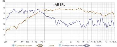
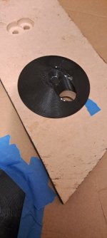
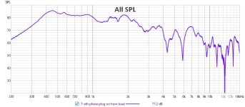
Despite printing and testing a slew of different ports, cone fillers and slots to push the response higher, the best compromise I seem to be able to achieve with 4 EQ5s8s in my small prototype horn (thanks Bwaslo for SynergyCalc!) is attached (note no electrical filters are applied). I can’t quite push up to 1khz to meet the DE250 as high as I’d hoped which is a little bit of a dissapointment. My Hornresp sim is roughly the right shape but the high and low corners are much lower in reality. Not sure why I’m not closer to the sim (assume I messed up the model somewhere) but it looks like a somewhat promising bandpass and acoustic rolloff can be achieved on these mids? I might just have to live with a crossover around 900hz if I want to use these 5” drivers. The MEH horn design was intended to sit above a direct radiating or horn loaded kick, but it needs a lot more work (and possibly a BMS 4550 or a 1.4 inch comp).


Despite printing and testing a slew of different ports, cone fillers and slots to push the response higher, the best compromise I seem to be able to achieve with 4 EQ5s8s in my small prototype horn (thanks Bwaslo for SynergyCalc!) is attached (note no electrical filters are applied). I can’t quite push up to 1khz to meet the DE250 as high as I’d hoped which is a little bit of a dissapointment. My Hornresp sim is roughly the right shape but the high and low corners are much lower in reality. Not sure why I’m not closer to the sim (assume I messed up the model somewhere) but it looks like a somewhat promising bandpass and acoustic rolloff can be achieved on these mids? I might just have to live with a crossover around 900hz if I want to use these 5” drivers. The MEH horn design was intended to sit above a direct radiating or horn loaded kick, but it needs a lot more work (and possibly a BMS 4550 or a 1.4 inch comp).
Attachments


Last edited:
that is actually quite good for an unequalized response...equalize it and give it a listen
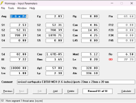
If your ports are 23x23x20mm as noted in your Hornresp screen shot, your length is 2.3cm and you have one port per driver as your cad shows, how do you get 57cm^2 for port area? I would think 18.4cm^2. Did you include the DE250 throat and phase plug length in your model? If you simulate a shorter distance between the midrange entry points to the back of the horn than exists in reality, that will make the notch in the response from the reflection move up in frequency. Your driver inductance is much lower than the inductance given in the driver specs which would also make the sim show more HF output. I would also probably simulate this in 4pi, not 2. However even changing all this it still doesn't do a great job matching your measurements. It still has a HF corner around 1.5kHz as compared to your measurement which looks like more like 1k. You might look at your front chamber volume to verify that's correct.
I can’t quite push up to 1khz to meet the DE250 as high as I’d hoped which is a little bit of a dissapointment.
Hmm, your Cms based on published specs s/b 1.77
Per this post and using the VC dia. = ~34400/pi/3 cm = ~3650 Hz, then tune the chamber to (503*3650)^0.5 = ~1355 Hz upper limit, which requires Vtc = ~180, reducing passband eff. to ~100 dB or if flat to 1 kHz @ 100 dB, then need to at least double your 320 Vtc.
I would think 18.4cm^2
Couple of clangers there, oops! Thanks for picking those up!Your driver inductance is much lower than the inductance given
 Clearly my Vtc needs attention also ...thanks @GM for the calculations 🙂 I'll review and revise the model.
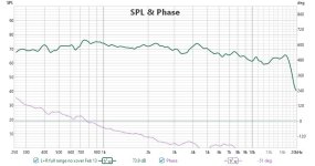
At the moment, no I haven't included the DE250 phase plug length in my modelled distance from throat. The reflection notch is high enough i think to not be causing my early rolloff which is present even when I measure at the port exit with the baffle inset removed from the horn or on a separate baffle. My ports are angled through the 3d printed horn and the port taps are just over 4cm from the compression driver bug screen. This is probably too close in reality (the mid ports do seem to significantly impact the HF response) but I've stuck it that close in order to preserve the horizontal port to port 1/4 wavelength distance. Currently they're nearly 9cm apart which I calculate is bordering on too distal if I'm looking for them to play up to 1khz (and beyond). I'm considering moving them out of the corners just to bring them closer together. I think Bill discussed doing this on one of his MEHs.
To be honest I haven't really looked at my hornresp model in a while but instead have been printing and testing ports and phase plugs, partly because it's given me a good sense of the impact of port length, size and Vtc. It's been a bit unscientific but I don't really see it as wasted effort, just learning. I can actually push the response from the bandpass ports higher, but the response isn't pretty after 900hz (I'm guessing I'm getting cancellations across the cone?) so I went back to a flat baffle. The attached measurement is taken outside the horn.
Attachments

Last edited:
there is another mechanism by which the upper limit is limited, so to speak - cancellation from sound arriving at the hole into the horn flare from most distant parts of the cone out of phase with that from nearby portions of the cone.
As frequency rises, there will be cancellation as the distance approaches half a wavelength. I've seen the problem myself with 8" driver. I wouldn't expect it with a 5" driver but your cone filler may increase the travel distance enough to make it a problem. If the Vtc isn't the limiting factor, then removing the cone filler might extend your upper limit.
What I did with my 8" driver was make an angled tunnel in the cone filler so it collected sound from the center of the cone and tunneled it over to the edge for penetration through the cone flare..
This is a great suggestion! I was actually looking at Patrick Bateman's metlako port design where he has a port opening at the vertex of the filler roughly the size of the dustcap expanding to a long, thin slot in the horn wall. This might address both the port tap disruption of the HF response and block any cancellations from the edge of the cone. The worst dip when I try to extend the upper corner seems to be at about 1.3 khz, the half wavelength of which is just over 5" so the out of phase cancellation you describe seems quite plausible here - since the ports are near one edge of the cone, the distance from the most distal side of the cone through the port could very easily equal about 5 inches. Since it's quite a broad dip, I'm wondering if that's cancellations from different parts of the cone which are different distances from the port exit?... was make an angled tunnel in the cone filler so it collected sound from the center of the cone and tunneled it over to the edge
Oh wow, that's pretty cool! Is that with or without a cone filler (or doesn't it matter so much for this particular pressure modelling?) 🙂a dip closer to 2kHz. Below there the pressure distribution in the front chamber seems pretty uniform.
Last edited:
- Home
- Loudspeakers
- Multi-Way
- Suitable midrange cone, for bandpass mid in Unity horn