You're welcome!
Hmm, at ~3.25/6.5" I don't see how these can be due to the driver, but look at its factory measured response and it near enough matches your measurement from ~500 Hz out to its ~1355 Hz upper limit.

That's without anything filling the front chamber. I have one with the front chamber filled drawn and in the queue.Oh wow, that's pretty cool! Is that with or without a cone filler (or doesn't it matter so much for this particular pressure modelling?) 🙂
That's very true actually, thanks for the reality check! 😲 I think when I surveyed these drivers that factory curve did look pretty lumpy but could live with a response that rolled off a bit above 1khz. My immediate goal is to just get that second peak in the bandpass response (currently between 800 and 900hz) up a little bit higher before it rolls off. All this is prefaced by saying I'm really in new territory and many of my assumptions are likely wrong! lolbut look at its factory measured response and it near enough matches your measurement from ~500 Hz out to its ~1355 Hz upper limit.
My wider goal, and particularly the goal of posting in this thread was to validate (or discount) this driver as a viable option for MEH builders. As we know, the current choice of sealed back mids which fit the bill is pretty narrow.
Amazing! thankyou @John Sheerin 🙂 Are you using Akabak or something like that?I have one with the front chamber filled drawn and in the queue.
Last edited:
there is another mechanism by which the upper limit is limited, so to speak - cancellation from sound arriving at the hole into the horn flare from most distant parts of the cone out of phase with that from nearby portions of the cone.
As frequency rises, there will be cancellation as the distance approaches half a wavelength. I've seen the problem myself with 8" driver. I wouldn't expect it with a 5" driver but your cone filler may increase the travel distance enough to make it a problem. If the Vtc isn't the limiting factor, then removing the cone filler might extend your upper limit.
What I did with my 8" driver was make an angled tunnel in the cone filler so it collected sound from the center of the cone and tunneled it over to the edge for penetration through the cone flare..
A simple loft from a center collection point to the desired port output is how I did my lower mids.
https://en.toutlehautparleur.com/catalog/product/view/id/36539https://faitalpro.com/en/products/LF_Loudspeakers/product_details/index.php?id=401005110
4fe44
New neo 4” that in my first simulation seems like a contender/alternative to B&C 4ndf34.
First price indicator, it usually goes up a little after the first shipment to thlp but definitely cheaper than 4ndf34
Great to see that can work! 😀 In my frenzy of port printing i did try a loft from a volcano style port filler to the port exit but it wasn't all that close to the dust cap and it didn't really seem to do the trick. Yours seems to have quite a big gap too actually but i imagine your xmax is fairly high on those drivers.simple loft from a center collection point to the desired port output
well don't make light of the 4FND34's 3.8mm Xmax and high power handling. It stands out among 4" drivers and worth its extra cost if your design makes use of its higher excursion.
I too used a volcano style filler but I blocked the top and let sound enter the cone from a ring opening somewhat down from the top so that coming off the dustcap didn't have a short cut into the filler.
I too used a volcano style filler but I blocked the top and let sound enter the cone from a ring opening somewhat down from the top so that coming off the dustcap didn't have a short cut into the filler.
Absolutely its a big gap to allow for the excursion it need from ~150Hz-300Hz and a 6mm xmax. But the same principle can be fine tuned with spacers around the adapter.
Wow, ok now i wouldn't have thought to do that...very novel. 🙂 Do you happen to have an image you would be willing to share ? Forgive me if you've done so already... I think ive read most of your MEH posts from the last decade or so but i could have missed it!too used a volcano style filler but I blocked the top and let sound enter the cone from a ring opening somewhat down from the top
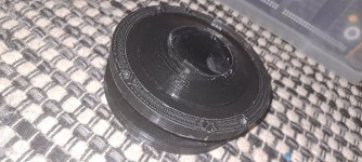
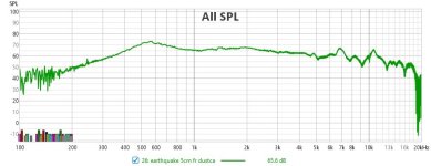
Fwiw my "volcano" was a fail, but not to say a better implementation wouldn't work. Again just for interest my measurement of this sealed back driver in open air (not sure i can say free air for sealed back) 5cm in front of the cone is attached too.
Attachments
Last edited:
My solution is embarrasingly crude but it was just a prototype and it worked. I went with 4 4" drivers instead of 2 8"ers for the next version

the view from under the volume plug which sat on top of angled elliptical holes in the horn flare next to a side flare, near the throat

the view from under the volume plug which sat on top of angled elliptical holes in the horn flare next to a side flare, near the throat
This is another variation that works to reach 1,5kHz in my coentrant adapter for a 6” coaxial.
Ignore the clearance, it’s been adjusted.
Hey guys, I bought a couple of DFM-2535R00-08 from the recent group buy. I was thinking of making a MEH style speaker with them. I have started researching on MEH and think I read most of the threads on diyaudio. I'm still struggling with hornresp but trying 😛
Først question:
Has anyone tried this driver:
https://www.scan-speak.dk/product/10f-4424g00/
as a midrange for a MEH?
According to the 2*fs/qes it scores 562 which should be pretty good right? Or did I miss something?
Second question:
Wouldn't the attached responses be considered reasonable for s mid range to cross at 1599ish hz? The graph is without any eq and it's the SB65 full range driver. This driver shouldn't work very well according to the 2*fs/qes though?
Sorry for the probably stupid qiestions, but every beginning is hard xD
Edit: the bright lines in the grid are 5dB steps.
Attachments

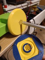
This is cool. Any more details?View attachment 1427211
This is another variation that works to reach 1,5kHz in my coentrant adapter for a 6” coaxial.
View attachment 1427214
Ignore the clearance, it’s been adjusted.
It’s my take on their coentrant mid-high technology https://renkus-heinz.com/core-technologies/
It uses a 6” redcatt coaxial.
Cone ~600-1500Hz
I made a 1” version and a 2” both with conical expansion from the comp driver throat diameter and to the designated size and tried them on clones of https://jblpro.com/products/2380A
And the 1” on a http://kiirojbl.web.fc2.com/patent/PT_WaveGuide.pdf


It uses a 6” redcatt coaxial.
Cone ~600-1500Hz
I made a 1” version and a 2” both with conical expansion from the comp driver throat diameter and to the designated size and tried them on clones of https://jblpro.com/products/2380A
And the 1” on a http://kiirojbl.web.fc2.com/patent/PT_WaveGuide.pdf
Greets!According to the 2*fs/qes it scores 562 which should be pretty good right? Or did I miss something?
Wouldn't the attached responses be considered reasonable for s mid range to cross at 1599ish hz?
Yes for horn loading, which is basically all that's telling us and no because we're working between the driver's 92 Hz Fs - 2 cm VC dia. = 34400/pi/2 = ~5475 Hz to find its theoretical upper XO point limit.
(92*5475)^0.5 = ~702 Hz mean
ln(5475/702)/ln(2) = ~2.96 octaves*702 = 2080 Hz upper limit and if you're using accurate measured specs, then all you need to do is look where the polars are breaking away from the dustcap to quickly find its ~ upper limit, i.e. from this point on the rest of the HF BW is radiating off it.
My answer is yes, that is a very good driver for use as a mid but that isn't the point of my post. If you look far enough back in this thread you will find me arguing against the use of that simplistic formula as an indicator of suitability. I think I argued then that you should just throw the T/S params into an HR model and see what it says. I would repeat that today but add that if you struggle with HR's MEH model, just do a simulation of the driver in a bandpass configuration, which is much simpler. If HR bandpass model is challenging, try Vituix enclosure sim for a bandpass type 1. It took me all of 10 minutes this AM to do the simulation.

First I modeled the 4 drivers as closed box to find a good volume for the bandpass box rear chamber
Next I dialed in a very small volume representing the volume of air trapped under the driver cones for the box front chamber
Then I set the vent length to about half an inch and the diameter to 1" and set the number to 4.
By this time I had a nice peaked response extending past 1 khz so I dialed in some filters to tame that peak and add a high pass

so why is that formula insufficient?
the low end limit will be determined by either the Xmax of the driver or the vent velocity determined by the area of the ports into the horn at maxSPL
the upper limit will be determined by the bandpass acoustic low pass filter which you can "tune" via volume of air trapped under the cone and the vent length and area.
One other nice thing about using a small full range driver rather than a small woofer is it doesn't have any wild breakup peaks that can leak through the port holes. These also have more Xmax than e.g. closed back midranges and thus support a lower low frequency limit.
First I modeled the 4 drivers as closed box to find a good volume for the bandpass box rear chamber
Next I dialed in a very small volume representing the volume of air trapped under the driver cones for the box front chamber
Then I set the vent length to about half an inch and the diameter to 1" and set the number to 4.
By this time I had a nice peaked response extending past 1 khz so I dialed in some filters to tame that peak and add a high pass
so why is that formula insufficient?
the low end limit will be determined by either the Xmax of the driver or the vent velocity determined by the area of the ports into the horn at maxSPL
the upper limit will be determined by the bandpass acoustic low pass filter which you can "tune" via volume of air trapped under the cone and the vent length and area.
One other nice thing about using a small full range driver rather than a small woofer is it doesn't have any wild breakup peaks that can leak through the port holes. These also have more Xmax than e.g. closed back midranges and thus support a lower low frequency limit.
Last edited:
Here are some results from 3D FEA simulations of some aspects of midrange geometry. I started off modeling rrobot's geometry from hornresp as a square horn with his port geometry and a rough front chamber based on the available dimensions of the earthquake driver. Then I changed a bunch of things to see how the response would be effected. I'm modeling only the air volumes in and around the speaker and applying a constant acceleration uniformly across the driver's cone. There's no attempt to model any effects of the driver's response due to cone breakup or its electro-mechanical parameters. What this type of data is good for is seeing the effects of the 3 dimensional geometry you're putting the driver in and seeing relative changes between different geometries. It's also good for looking at directivity, but I didn't pull that data out here. I'm just showing the response in free space at about 0.5m in front of the mouth of the horn. Here's what one of the geometries looks like plus a closer view of the air in front of the driver and the port. The highlighted blue areas are where I've applied the acceleration to the cone (along the driver's axis) as a stimulus for the simulation. It's a 1/4 symmetry model, so even though there's only 1 driver the model is simulated 4 drivers symmetrically arranged around the horn.


First I looked at a rectangular port entering the horn tangent to one of the walls and compared that to an equal area round port. Here's a plot showing the simulated responses on top and the difference between them on the bottom. All these plots run from 200Hz to 4kHz.
So it looks like a rectangular port has about 0.5dB more output than a round port and shifts around the resonances in the horn slightly.

Next I looked at the rectangular port (more or less square - 20x23mm) vs an equal area but long and narrow port (so about twice the length along the corner of the horn but half as wide). The narrow port has about 0.5dB more output at higher frequencies (by which I mean around 600-1.5kHz).

Here's the original rectangular port which comes in perpendicular to the wall of the horn compared to the same port but coming in at a 45 degree angle to the horn wall (it's actually only 45 degrees when viewed from the front or back). This is what's shown in the example model image. This seems to pickup 1.5-2dB which is interesting. The length is the same going from the point of the corner, so arguably the port length is changing slightly.

The ports entering perpendicular to the horn wall force the ports to be somewhat close to the perimeter of the driver in order to not have the drivers run into each other. The port entering at 45 degrees doesn't do that, so the port ended up closer to the driver's center. Moving the driver so the port enters the front chamber closer to the edge of the driver gives about a 3dB+ reduction in output.

If I take that 45 degree port and flare its entrance towards the driver's center, that gives me an extra 1dB of output.

The 45 degree entrance port generally seems like a winner so let's keep going with that. If I put a filler plug in the front chamber to follow the surface of the cone, that makes the port longer (the driver stays in the same location, so now the port has to extend further to reach the front chamber). But having the small front chamber shifts the resonances around in the system quite a bit and moves the first pressure null in the front chamber down from around 2k to 1.5kHz. You also get a lot more higher frequency output (2-4kHz) which I would consider a negative given you wouldn't want to use this above maybe 1.3kHz.

If I take that smaller front chamber geometry and flare the port inlet like I've seen people do, that shifts that null up a bit but doesn't seem to help a ton.

However if I take that small front chamber and make a single slot circumferential phase plug going into the rectangular port, I can smooth out that null from the front chamber. I just drew something here - no calculations, so I'd assume I could smooth this out more if I actually spent some time on it.

If I take the original 45 degree port and change it to be the longer narrower port, I get a marginal improvement of <0.5dB. Just speculating but maybe the improvement from round to rectangular to narrow to 45 degree entrance is all on a spectrum of getting improvements from getting the port into the corner and here we've gotten the last of that.

Here's looking at different inlet port flares on the 45 degree long narrow port. First I flared it in only the plane along the corner of the horn towards the driver center, good for about 0.5dB. Then I additionally flared it to both sides so opening across more of the driver cone which gave a 2-3dB improvement at high frequencies. Then I made a lofted surface that flared the port inlet out to a circle equal to the diameter of the surround of the driver. This gave more high frequency gain but less gain below 1kHz and lower compared to the port flared horizontally, so depending on what you're going for maybe there's a happy medium between those two that could be optimized for.

Then I took that geometry where the port flares to cover the entire driver cone and tried different port lengths (roughly half and double the port length I had been simulating). This shifts the front chamber resonance around 2kHz and the low frequency resonance around which also effects the output across most of the pass band. I would say shorter seems better.

Last, I tried varying the length of the section of horn between the midrange ports and the small end of the horn. This one surprised me. I expected to see more of an effect of nulls in the response moving around. You do see that just below 2kHz but not a very big shift. For the half length geometry, I cut off the small end of the horn midway between the midrange port entrance and the small end of the horn. For the longer length, I actually drew in a completely made up 2 slot phase plug going out to a 50mm tweeter diaphragm and front chamber. Note that my frequency spacing is not super tight so I wouldn't read too much into the notches in the response being deeper or shallower around 2kHz. It could just be an effect of where the nulls in the response fell in relation to where my simulated frequency points were.

Anyway, I hope someone finds this useful. I certainly found it interesting. I might have to hack the back off my old unity horn and 3d print something to try out some of these ideas. Also, this is only half to one third of the full picture. The other interesting thing to look at would be the effects of all of this on the tweeter's response. I need to finish building a more powerful computer to be able to look at that. It could also be interesting to look at air velocity levels through these different ports (which would give different max output limits) although they're all the same area so I would imagine there wouldn't be huge differences there.
First I looked at a rectangular port entering the horn tangent to one of the walls and compared that to an equal area round port. Here's a plot showing the simulated responses on top and the difference between them on the bottom. All these plots run from 200Hz to 4kHz.
So it looks like a rectangular port has about 0.5dB more output than a round port and shifts around the resonances in the horn slightly.
Next I looked at the rectangular port (more or less square - 20x23mm) vs an equal area but long and narrow port (so about twice the length along the corner of the horn but half as wide). The narrow port has about 0.5dB more output at higher frequencies (by which I mean around 600-1.5kHz).
Here's the original rectangular port which comes in perpendicular to the wall of the horn compared to the same port but coming in at a 45 degree angle to the horn wall (it's actually only 45 degrees when viewed from the front or back). This is what's shown in the example model image. This seems to pickup 1.5-2dB which is interesting. The length is the same going from the point of the corner, so arguably the port length is changing slightly.
The ports entering perpendicular to the horn wall force the ports to be somewhat close to the perimeter of the driver in order to not have the drivers run into each other. The port entering at 45 degrees doesn't do that, so the port ended up closer to the driver's center. Moving the driver so the port enters the front chamber closer to the edge of the driver gives about a 3dB+ reduction in output.
If I take that 45 degree port and flare its entrance towards the driver's center, that gives me an extra 1dB of output.
The 45 degree entrance port generally seems like a winner so let's keep going with that. If I put a filler plug in the front chamber to follow the surface of the cone, that makes the port longer (the driver stays in the same location, so now the port has to extend further to reach the front chamber). But having the small front chamber shifts the resonances around in the system quite a bit and moves the first pressure null in the front chamber down from around 2k to 1.5kHz. You also get a lot more higher frequency output (2-4kHz) which I would consider a negative given you wouldn't want to use this above maybe 1.3kHz.
If I take that smaller front chamber geometry and flare the port inlet like I've seen people do, that shifts that null up a bit but doesn't seem to help a ton.
However if I take that small front chamber and make a single slot circumferential phase plug going into the rectangular port, I can smooth out that null from the front chamber. I just drew something here - no calculations, so I'd assume I could smooth this out more if I actually spent some time on it.
If I take the original 45 degree port and change it to be the longer narrower port, I get a marginal improvement of <0.5dB. Just speculating but maybe the improvement from round to rectangular to narrow to 45 degree entrance is all on a spectrum of getting improvements from getting the port into the corner and here we've gotten the last of that.
Here's looking at different inlet port flares on the 45 degree long narrow port. First I flared it in only the plane along the corner of the horn towards the driver center, good for about 0.5dB. Then I additionally flared it to both sides so opening across more of the driver cone which gave a 2-3dB improvement at high frequencies. Then I made a lofted surface that flared the port inlet out to a circle equal to the diameter of the surround of the driver. This gave more high frequency gain but less gain below 1kHz and lower compared to the port flared horizontally, so depending on what you're going for maybe there's a happy medium between those two that could be optimized for.
Then I took that geometry where the port flares to cover the entire driver cone and tried different port lengths (roughly half and double the port length I had been simulating). This shifts the front chamber resonance around 2kHz and the low frequency resonance around which also effects the output across most of the pass band. I would say shorter seems better.
Last, I tried varying the length of the section of horn between the midrange ports and the small end of the horn. This one surprised me. I expected to see more of an effect of nulls in the response moving around. You do see that just below 2kHz but not a very big shift. For the half length geometry, I cut off the small end of the horn midway between the midrange port entrance and the small end of the horn. For the longer length, I actually drew in a completely made up 2 slot phase plug going out to a 50mm tweeter diaphragm and front chamber. Note that my frequency spacing is not super tight so I wouldn't read too much into the notches in the response being deeper or shallower around 2kHz. It could just be an effect of where the nulls in the response fell in relation to where my simulated frequency points were.
Anyway, I hope someone finds this useful. I certainly found it interesting. I might have to hack the back off my old unity horn and 3d print something to try out some of these ideas. Also, this is only half to one third of the full picture. The other interesting thing to look at would be the effects of all of this on the tweeter's response. I need to finish building a more powerful computer to be able to look at that. It could also be interesting to look at air velocity levels through these different ports (which would give different max output limits) although they're all the same area so I would imagine there wouldn't be huge differences there.
This is useful and interesting, not least because making good simulations of this nature is not open to a lot of people.Anyway, I hope someone finds this useful.
For me what would make it even more useful is if you could show screenshots of the different CAD geometries you are describing as I am struggling to visualise everything you are describing.
- Home
- Loudspeakers
- Multi-Way
- Suitable midrange cone, for bandpass mid in Unity horn