A small update again. I shortened the supply wires and added a 220u bipolar cap in parallell with the std input cap, but can't say I hear much difference. Bass is ok, but still not as good as LJM MX50SE. It has some punch, but lacking a bit control in the low register. Well, I don't expect it to be the best at everything. it is a good all-rounder now, and very good for mids and treble. I will probably end up using it for mids or treble in my active setup too.
A sidenote:
I noticed a funny thing with the variable current on the input transistor today. With the cancellation balance between the outputs slightly off (little bit extra 2nd harmonic) I was able to reduce that second harmonic by adding some current on the input transistor with the ccs. However, when the balance of the outputs is optimal for low distortion, the added current on the input transistor increases second harmonic distortion. Seems one can balance out the other.
I'm not sure if I should post this question here, or in the JLH1969 thread.. It is regarding the floating ground, so it relates to the sublimed modification.. I hope it's ok to post here?
I have also converted the PNP JLH to floating ground now, and I can see some swinging/oscillation in the ground voltage when I quickly increase/decrease input signal. The oscillation is damped('rings out' in a couple of periods), and around 1Hz. Capacitance on the main capacitors for the floating ground is more than 15mF each, but C4 is only 200uF at the moment, and input capacitor is 47uF.
Am I correct in assuming that increasing C4 should make it more stable/slow?
divizka: I'm not familiar with all the terms.. do you have an example schematic?
Alley and Atwood, Electronic Engineering, 2nd ed. 1966 p466.
I did not trust the LF performance of such a design, but simulated it a while ago out of curiosity. Indeed there was an undesirable low frequency damped oscillation. It was ameliorated using 1mF -100 ohm decoupling filters on the input bias chain, to a tolerable level, and yes you could not use a single supply for two channels.
I did not trust the LF performance of such a design, but simulated it a while ago out of curiosity. Indeed there was an undesirable low frequency damped oscillation. It was ameliorated using 1mF -100 ohm decoupling filters on the input bias chain, to a tolerable level, and yes you could not use a single supply for two channels.
I tried the bigger cap on C4, but it's the same. Could you post a sketch of the arrangement you mention?
EDIT: Something like this? https://www.diyaudio.com/forums/solid-state/329553-sublimed-jlh1969-9.html#post5911995
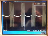
Here is a screenshot of bursts and the swing between bursts. I guess the moving midpoint would not matter much until the amp approaches clipping?
EDIT: Something like this? https://www.diyaudio.com/forums/solid-state/329553-sublimed-jlh1969-9.html#post5911995
Here is a screenshot of bursts and the swing between bursts. I guess the moving midpoint would not matter much until the amp approaches clipping?
Attachments
Last edited:
I see the same oscillation at startup too, but with the input open there is no oscillation, leads me to think the variation is fed back trough the input, causing the big swings.
Maybe a smaller input cap, or some kind of 'filtering' on the ground side of the input would improve it?
EDIT: Tried a smaller input cap, and the oscillation is gone. Guess it's a matter of fine tuning the input cap..
Maybe a smaller input cap, or some kind of 'filtering' on the ground side of the input would improve it?
EDIT: Tried a smaller input cap, and the oscillation is gone. Guess it's a matter of fine tuning the input cap..
Last edited:
I see the same oscillation at startup too, but with the input open there is no oscillation, leads me to think the variation is fed back trough the input, causing the big swings.
Maybe a smaller input cap, or some kind of 'filtering' on the ground side of the input would improve it?
EDIT: Tried a smaller input cap, and the oscillation is gone. Guess it's a matter of fine tuning the input cap..
I think you can blame the start up issue on the use of a switch-mode power supply following which it settles.
The subjective perception of loss of bass is likely to be due a supply output impedance which is not adequately low in that frequency range.
Also there is no r.f. filtering on the input.
Member
Joined 2009
Paid Member
Whether floating ground or not, there are going to be at least two capacitors in the speaker current path. With floating ground there's a capacitor from each rail to the speaker return point (like a split rail design) and with the non-floating there's the output cap and the rail-to-ground cap. In both cases you have two caps, both outside of the feedback loop. So why would they sound different ?
The floating ground puts power supply ripple and speaker return current in the same pair of caps. The non-floating version doesn't mix signal and power supply ripple in the main output cap. Is this is enough to explain it - I don't think so.
I'm surprised people can hear a difference and would like to know why.
Perhaps it matters where you 'ground' the feedback shunt capacitor - ideally it should be connected to the return side of the speaker not the input signal ground because the series - shunt feedback resistors are a potential divider connected across the speaker ?
Last edited:
I'm definitely no expert, but to me it looks like both sides of the speaker terminals are in the feedback loop with the floating ground (ref to the sublimed schematic in the first post). One resistor of the feedback divider is connected to the output (+ of the speaker), and the other resistor is connected to the floating ground (- of speaker). This to me looks like both are in the loop, so whatever happens with the current through the capacitors/voltage would be compensated for? Or is the same ground reference for the input cancelling this effect or even making it worse?
- Home
- Amplifiers
- Solid State
- sublimed JLH1969