no , mine, pulls the bias of the input transistor from the collector about two extra ma. If you do it by reducing the collector resistor that the gain will be reduced .Is it in principle the same as this? (Q5/Q6)
I thought to be the inventor of the single floating supply , but no Onkio has done it decade ago for its prestigious amplifiers. The advantage is in the power supply occupation/idle use . Take the double split supply in class ab . When the output pushes with positive voltage the load loops its current from the positive supply only . The positive PSU which was resting suddenly is ask to huge power and when negative supply is solicitated it must shut down immediately . In single floating supply there one which at both polarities is solicited . In single supply with output capacitor , the negative current is due to discharge of the capacitor while the power supply is idle . Such power supply gives the best powerful bass , without having an armada of reservoir capacitors specially with switching power supplies.Can someone please explain what is the difference between the floating supply and a true symmetrical supply (like the later version of the JHL)?
In the original asymmetrical supply the loudspeaker was well protected from the risk of an unexpected dc-surge by the output capacitor. In this new approach, the loudspeaker would benefit from a protection circuit. Is that correct?
I have done the mod, and checked that they function with scope and low Iq setting. Only thing I saw, was that it looked like the noise was higher now on the scope after this mod. I used the BC337-40, could the high gain give more noise?
I will do a new 'calibration' with Arta FFT, and listen to them in the evening.
I will do a new 'calibration' with Arta FFT, and listen to them in the evening.
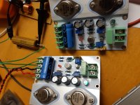
Attachments
Last edited:
None of these articles are related to single floating supply.Also Wireless World September and October 1980 floating bridge by R.M.Brady
Thanks for your reply in post 102, Kokoriantz.
And what is your view on my second question:
In the original asymmetrical supply the loudspeaker was well protected from the risk of an unexpected dc-surge by the output capacitor. In this new approach, the loudspeaker would benefit from a protection circuit. Is that correct?
And what is your view on my second question:
In the original asymmetrical supply the loudspeaker was well protected from the risk of an unexpected dc-surge by the output capacitor. In this new approach, the loudspeaker would benefit from a protection circuit. Is that correct?
Which simulator are you using? Thank you ...A 100uf grounding the bases can help reduce the noise .
Tina Ti free download from Texas Instrument.Which simulator are you using? Thank you ...
i
Yes , no need dc protection as the speaker is capacitor coupled.Thanks for your reply in post 102, Kokoriantz.
And what is your view on my second question:
In the original asymmetrical supply the loudspeaker was well protected from the risk of an unexpected dc-surge by the output capacitor. In this new approach, the loudspeaker would benefit from a protection circuit. Is that correct?
Ok, I have done some measurements and adjustments after adding the current limiting circuit. It seems the DC balance changed, so I could not get Iq higher than 1A, and I had to do a lot of turns on the offset trimmer too. I changed back R8 to 220ohm to get higher Iq, and adjusted for lowest distortion. Iq is now abt 1,3A after warming up.
On the measurement IMD is higher than the measurement I did here https://www.diyaudio.com/forums/solid-state/3075-jlh-10-watt-class-amplifier-562.html#post5969996
Now the 1kHz peak is a little bit higher, and there is another peak at 2kHz almost the same level as 1kHz on the two tone FFT, so I would say it measures worse than before.
I have only listened a little bit, and first impression was that it sounds a little bit brighter, but I'm not sure... First impression is that sound is good, but I need to give it some time.
The plan is to add the floating ground next. As I would like to do one change at a time, I wonder if it's ok to just add the coupling capacitors, remove C3, connect R4 to the virtual ground, and reference the input signal to the new virtual GND?
When I'm looking at your schematic, I think I understand that part. What is the reason for the rearrangement of the input with a 10k input impedance? And what is Rb (3,9k) for? Balancing some DC currents?
Also changing R8/KT2/R7 to increase the current here? In this case I can not use trimmers to do 'my thing' adjusting the current and balance between the transistors. Too high power for trimmers I think?
post 113: Yes , no need dc protection as the speaker is capacitor coupled.
Thanks for confirming (My learning: I read the word 'yes' in the above sentence as 'No').
More important to prevent misunderstanding: the ground symbol of the power supply has a different meaning (ground at the mains connection) than the ground symbol in the amplifier schematic (= virtual ground). They should not be connected. Correct?
If correct, the case should be connected to the mains earth, and the '0 V' of the schematic can - and should - be connected to the case. The input connector and loudspeaker connector should then be isolated from the case. Correct?
Last edited:
I have only listened a little bit, and first impression was that it sounds a little bit brighter, but I'm not sure... First impression is that sound is good, but I need to give it some time.
Yes, I think the sound was more mellow/laid back before, now transients sound sharper, and overall a little bit brighter sound. Not sure which I prefer yet.
As you noticed a difference in sound you can adjust at your taste by Ra 8.2k to have more or less definition. The 10k input load is in case the source has also capacitor output , than the 100uf capacitor can not polarize . The biasing resistors you already adjusted , once finished replace the low current adjust by a fix resistor . Rb 3.9k is indeed a pull to provide current to 100 ohm in case the speaker is not branched .Yes, I think the sound was more mellow/laid back before, now transients sound sharper, and overall a little bit brighter sound. Not sure which I prefer yet.
The virtual ground becomes the common ground earthen to the chassis along with the other channel ground to the ground of the input preamp/dac . As the two channels have their virtual grounds linked than each channel need its own floating supply .post 113: Yes , no need dc protection as the speaker is capacitor coupled.
Thanks for confirming (My learning: I read the word 'yes' in the above sentence as 'No').
More important to prevent misunderstanding: the ground symbol of the power supply has a different meaning (ground at the mains connection) than the ground symbol in the amplifier schematic (= virtual ground). They should not be connected. Correct?
If correct, the case should be connected to the mains earth, and the '0 V' of the schematic can - and should - be connected to the case. The input connector and loudspeaker connector should then be isolated from the case. Correct?
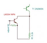
Jlh needs to function with very low current biased input transistor. This error comparing stage functions with IC/Vbe character of the transistor. Transistors need several milliamps bias to polarize the base emitter diode in more linear operating point . There is a transistor specialized for low currents is ksa992 . Probably it is the best choice.
- Home
- Amplifiers
- Solid State
- sublimed JLH1969