But whats the point? Why use shitty old caps when new good ones costs close to nothing? Get a grip!
> check it out on falstad
It appears Falstad does not model grid current for positive grid voltage.
I could try with a less-simplified tube model, or feed the dogs now. You're there, they are here, I know my duty. Maybe later.
It appears Falstad does not model grid current for positive grid voltage.
I could try with a less-simplified tube model, or feed the dogs now. You're there, they are here, I know my duty. Maybe later.
But whats the point? Why use shitty old caps when new good ones costs close to nothing? Get a grip!
Let's just assume that a highly subjective point exists. The subject of caps affecting the tone was fiercely debated all over the net. So, no need to reintroduce that debate here all over again.
Best.
oprtr
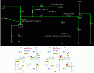
Here's simple 12AX7 stages, cap-coupled, with two values of cap leakage.
With "good" (1,000Meg) cap leakage, the second stage grid sits 0.1V positive of ground for -1.4V bias grid-cathode. That 2nd stage plate sits at 200V, what we expect for 300V 12AX7 100k 1.5k.
With "bad" (15Meg) cap leakage, the second stage grid sits 3.4V positive of ground, cathode at 3.2V for +0.2V bias grid-cathode. That 2nd stage plate sits at 88V, far below what we expect. The positive grid-cathode voltage means large grid current and LOW grid impedance (we expect 499k, we probably get 2k), and dropping further on positive grid swings, causing gross 2nd harmonic distortion.
FWIW, a 12AX7 with these values will NOT be "hurt" by 15Meg from a 200V preceding plate. The 0.04 milliWatts of unexpected grid dissipation is outside the ratings but won't cook the grid. It's just a bad amplifier. Try it.
Attachments
Thanks PRR.
It's obvious that the OP doesn't understand the sensitive nature of tube grids and conduction.
And korpberget's post is also an honest statement.
Why bother with old parts in any case?
Git RID of 'em!
It's obvious that the OP doesn't understand the sensitive nature of tube grids and conduction.
And korpberget's post is also an honest statement.
Why bother with old parts in any case?
Git RID of 'em!
I bought silica gel packets after a flood to insert inside equipment housings to speed the drying.
The packets came sealed in a paint can. To test capacitors for the effects of humidity, I tested ones unused off the shelf and then again after six months sealed in the paint can almost full of the packets. Not surprisingly the moisture level in the capacitors dropped. The silica gel packets can be dried out by baking.
So one should be able to dry out old wax paper capacitors.
That only leaves the question as "why bother?"
The valid answer is "I am curious and want to play."
Yes, it seems that you were not aware that any more than about 0.5uA can cause problems, and we prefer much less than that. Leaky coupling capacitors are a major cause of valve damage in old electronics.operater said:Guess I was not aware that 30µA of current leak can pose such a risk and liability as signal coupling in a tube amplifier, or can it actually!?
Shorting might be rare. Serious damage would be quite common. If you did a bit of Googling you could discover this for yourself - replacing the coupling cap to the output stage of an old radio or amplifier is one of the first things people do when renovating valve electronics. You still seem to be seriously considering putting in a component that anyone who knows anything would be removing.Anyone has any examples of wax paper actually shorting and slamming an output stage of a tube amp, and what are the odds for that ?
Exhibiting your ignorance of electronics in such a bold way does you no favours. Why not listen for a while instead of sharing your confusion with us?Also those 6V of leakage being itself @ 13µA cannot affect bias by 6V since the plate current is much higher. There is no way this measly 13µAmps can do anything at all to a plate running at 1 053 000 µAmps. Also, the grid stopper can conveniently drown away even higher leakages before they ever reach the grid itself.
I suggest you wear safety goggles and warn any pets and small children to keep their distance. You may invalidate your home insurance.Tell you what! I'm gonna slam couple of those in parallel with some power supply filter caps @ 270V and let them sit there for couple of months and see where they get with the values!
You should stop arguing and start listening, then you might learn something. You could begin by learning about how to bias a valve, especially cathode resistor bias. Then think about what might happen if the grid (which is normally around zero volts) is pulled up to a significant number of volts by a leaky cap - what does this do to anode current and hence anode dissipation? What happens when a valve overheats? Have you ever heard of thermal runaway?Guess the wax paper's hygroscopic nature is it's inevitable leaky destiny. But, the question remains, what components that operate in ranges of miliamps care about a few micro-amps of leakage if any do at all?
I am not arguing that values of those caps are great, but whether any kind of a circuit example really cares about such a low current leaking!
For the benefit of the OP, could you repeat this exercise using something like an EL84 or 6V6 output stage?PRR said:Here's simple 12AX7 stages, cap-coupled, with two values of cap leakage.
Also those 6V of leakage being itself @ 13µA cannot affect bias by 6V since the plate current is much higher. There is no way this measly 13µAmps can do anything at all to a plate running at 1 053 000 µAmps. Also, the grid stopper can conveniently drown away even higher leakages before they ever reach the grid itself.
It's not about grid current. But if you bias a, let's say, EL34 with a gm of 11 mA/V 6 Volts off it's nominal operation point, it will carry 66 mA more plate current. The question is: How long will this tube cope with that? And how long will it's periphery, especially the output transformer do?
Best regards!
For the benefit of the OP (and others) here is what people who are expert in restoring old radios think of leaky capacitors - especially waxed paper caps (referred to as 'waxies'):
'THAT' Capacitor. What is it? - UK Vintage Radio Repair and Restoration Discussion Forum.
In most cases they remove them on sight; they are known to be so unreliable that it is not even worth testing them.
I would replace an old coupling cap which puts more than 0.5V on the grid - that means about 100M resistance. I would ask for my money back if I bought a new cap which did that. Only a fool would put a cap below about 500M into a new circuit.
'THAT' Capacitor. What is it? - UK Vintage Radio Repair and Restoration Discussion Forum.
In most cases they remove them on sight; they are known to be so unreliable that it is not even worth testing them.
Yes, although it needs to be said that in the normal cathode bias case, elevating the grid by 6V does not mean 6V more bias because the cathode voltage will rise too and partly compensate. Which is one reason why cathode bias is popular.Kay Pirinha said:But if you bias a, let's say, EL34 with a gm of 11 mA/V 6 Volts off it's nominal operation point, it will carry 66 mA more plate current.
I would replace an old coupling cap which puts more than 0.5V on the grid - that means about 100M resistance. I would ask for my money back if I bought a new cap which did that. Only a fool would put a cap below about 500M into a new circuit.
I don't think he is a troll; I think he is genuinely ignorant. Unfortunately thus far he also appears to be arrogant too. That may change, let us hope so.
You should stop arguing and start listening, then you might learn something. You could begin by learning about how to bias a valve, especially cathode resistor bias. Then think about what might happen if the grid (which is normally around zero volts) is pulled up to a significant number of volts by a leaky cap - what does this do to anode current and hence anode dissipation? What happens when a valve overheats? Have you ever heard of thermal runaway?
Thank you again for keeping up with all of this mess. OFC I understand basic biasing concepts and valve operation in general. I have already built and tweaked one amp from a DIY kit and now trying something new from scratch. You can check out my second thread - much less futile exercise there.
I was clearly mistaken regarding the effects of leaking current on the next stage grid.
Here's simple 12AX7 stages, cap-coupled, with two values of cap leakage.
Thank you PRR not just for this but for so much detail down the road. I have really learned quite a bit since the start of the thread.
I'm trying to figure out why's the grid seeing this current instead of it going down the grid stopper. Because, isn't the grid stopper lower resistance to ground then the grid itself ?? What did I miss.
Thank you so much and I'm really sorry if you had to exercise things too basic here. I'm quite new to this, but I'm way too enthusiastic about vintage electronics to ignore those caps.
I bought silica gel packets after a flood to insert inside equipment housings to speed the drying.
The packets came sealed in a paint can. To test capacitors for the effects of humidity, I tested ones unused off the shelf and then again after six months sealed in the paint can almost full of the packets. Not surprisingly the moisture level in the capacitors dropped. The silica gel packets can be dried out by baking.
So one should be able to dry out old wax paper capacitors.
That only leaves the question as "why bother?"
The valid answer is "I am curious and want to play."
Thanks simon, I really may try this, combined with some operational voltage stressing. As for the why bother part, there is the tone effect as well. However this is hotly debated all over the place so no need to go in that direction. We know many people hear audible tone differences in caps, why is this so shocking to the community ? We cannot measure such subtle coloring third order harmonics by instruments anyway. Or can we ?
Exhibiting your ignorance of electronics in such a bold way does you no favours. Why not listen for a while instead of sharing your confusion with us?
Why hide ignorance if one seeks to learn ?
Also, when I said that the leak doesn't affect the plate current - I was refering to the plate current of the first driver, not the second stage one.
However I was obviously mistaken regarding it's effects on the plate current and bias of the power stage.
I will not be selling those caps unless I somehow manage to dry them out and fix the IR. Let's see what happens if I stress one long enough combined with the desiccation method.
Hope to hear from you all again.
Best.
oprtr
A valve grid only has high impedance when it is reverse biased - which is the normal situation in most non-faulty circuits. It acts like a diode. Put some voltage on it via a leaky cap and it can consume as much current as the grid leak resistor. However, unlike the resistor, the grid is nonlinear so it presents a nonlinear load to the source - which may be a somewhat higher impedance such as a small signal triode anode circuit. Hence you get significant distortion even if you don't ruin your valves.operater said:I'm trying to figure out why's the grid seeing this current instead of it going down the grid stopper. Because, isn't the grid stopper lower resistance to ground then the grid itself ?? What did I miss.
I am pleased that you are now starting to listen. I have learnt a lot from this forum and you can do the same.
Operator (Operater sp? 😀)
Well I think you're a troll, though I'd hope not. Theres some good guys here, no reason to annoy everyone, when some of the guys here are the most knowledgeable.
I am well aware of protocols for testing of capacitors and inductors/transformers/other windings.
It is, after all, my job.
Why don't you take your fancy pants attitude, and perform some real testing ?
Tan Delta and DF for starters, then see if they pass a flash test of (2xUn)+10% VDC for 10 seconds.
The last test was a joke. They wouldn't pass. I would try DC peak "flash" equivalent to RMS AC rating. Then check leakage again
I wonder how many will track and fail before you get there....
Last edited:
If you are new to vintage electronics and are eager to learn, I highly recommend watching some of the videos from the Mr. Carlson's Lab channel on YouTube. Tons and tons of excellent, well explained walk-throughs of vintage electronics repair.
Mr Carlson's Lab Channel
Specifically, I would recommend watching at least the first bit of his introduction to choosing capacitors to find out why old caps are likely to cause you to blow (expensive) tubes and (more expensive) output transformers.
Which Capacitor Do I Use?
Mr Carlson's Lab Channel
Specifically, I would recommend watching at least the first bit of his introduction to choosing capacitors to find out why old caps are likely to cause you to blow (expensive) tubes and (more expensive) output transformers.
Which Capacitor Do I Use?
Last edited:
Operator (Operater sp? 😀)
Well I think you're a troll, though I'd hope not. Theres some good guys here, no reason to annoy everyone, when some of the guys here are the most knowledgeable.
I am well aware of protocols for testing of capacitors and inductors/transformers/other windings.
It is, after all, my job.
Why don't you take your fancy pants attitude, and perform some real testing ?
Tan Delta and DF for starters, then see if they pass a flash test of (2xUn)+10% VDC for 10 seconds.
The last test was a joke. They wouldn't pass. I would try DC peak "flash" equivalent to RMS AC rating. Then check leakage again
I wonder how many will track and fail before you get there....
No idea how to perform those, especially not the first one. 😱 you got me there lol. I obviously had no Idea who I was dealing with.
No, really, my apologies. It genuienly surprised me however that one would have same IR expectations from trannies and caps.
Best.
operater, yes. no sp 🙄.
In both cases you need DC isolation, so very high resistance. Lower resistance indicates a fault, which usually requires replacing the component.
No idea how to perform those, especially not the first one. 😱 you got me there lol. I obviously had no Idea who I was dealing with.
For the record, I am no one important 😛
Tan delta isnt practical at home, without some specialist gear, so I was a little unfair really.
I would genuinely encourage you to DC test those caps at rated DC voltage, and test leakage again.
Maybe try burying them in silica gel for a few weeks, in a warm (not hot) place.
- Home
- Design & Build
- Parts
- Stumbled upon some coupling caps