Legis,
Let me take a look at resonance freq. I was just thinking how you were saying the horiz polars are not as even and I think this may be due to two things: (1) the large holes on the side due to the injection ports for the Deltalites, (2) you have a rectangular apex and probably no reason this coils not have been a square to match the round CD output. Wood putty will do wonders though. For prototyping and checking if the rounded corners will help quickly is to use modeling putty/clay. Then use wood putty and sand if that works. Awesome speed of build though.
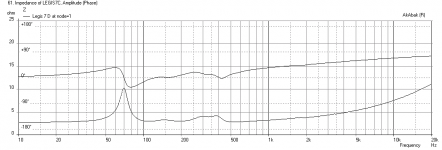
Edit: here is the impedance and phase for the dual Deltalites in the Synergy. It looks like the resonance peak is at 70Hz vs your measured value of 60Hz, but the feature of the small blip at 150Hz and the 300-400Hz are all there, there is even a tiny feature at 2kHz is showing up. Seems fairly accurate overall - I am actually pretty surprised how well this correlated. I adjusted the Q to simulate damping and when set at Q=0.12 (almost aperiodic) the impedance matches at 10 ohms. If set to Q=0.5 it is about 15ohms so still close.


Let me take a look at resonance freq. I was just thinking how you were saying the horiz polars are not as even and I think this may be due to two things: (1) the large holes on the side due to the injection ports for the Deltalites, (2) you have a rectangular apex and probably no reason this coils not have been a square to match the round CD output. Wood putty will do wonders though. For prototyping and checking if the rounded corners will help quickly is to use modeling putty/clay. Then use wood putty and sand if that works. Awesome speed of build though.
Edit: here is the impedance and phase for the dual Deltalites in the Synergy. It looks like the resonance peak is at 70Hz vs your measured value of 60Hz, but the feature of the small blip at 150Hz and the 300-400Hz are all there, there is even a tiny feature at 2kHz is showing up. Seems fairly accurate overall - I am actually pretty surprised how well this correlated. I adjusted the Q to simulate damping and when set at Q=0.12 (almost aperiodic) the impedance matches at 10 ohms. If set to Q=0.5 it is about 15ohms so still close.
Attachments
Last edited:
Yes, aperiodic was the word I tried to remember.🙂 That is quite remarkable similarity between sim & real thing for this kind of non-simple construction.
I found another synergy-build thread, that also has polar measurements: The very low budget DIY synergy horn build - Page 2 - AVS Forum
Polars (horizontal) seem on-par or somewhat worse than mine even though the builder had put the injection ports into the corners and has square apex with smoothed transition.
Last edited:
That is quite remarkable similarity between sim & real thing for this kind of non-simple construction.
This should give credence to using Akabak to model a Synergy injection port horn. I am pretty happy with the result and now have more confidence that we can use this model to help guide the optimization of the design if you wanted to do more to it. You can do something crazy like re-route the exit of your TH to slots near the mouth of your Synergy for true 40Hz to 15kHz "Point Source". 😀
I found another synergy-build thread, that also has polar measurements: The very low budget DIY synergy horn build - Page 2 - AVS Forum
Neat thread! Thanks. I did the same thing on my conceptual design for the tractrix synergy by porting the mids as a bass reflecx to the horn for extended bass. I guess that works in real life for this guy - it worked in Akabak for me.... I like how he used a simple dome tweeter instead of a CD. For home listening, this is fine...
Last edited:
This should give credence to using Akabak to model a Synergy injection port horn. I am pretty happy with the result and now have more confidence that we can use this model to help guide the optimization of the design if you wanted to do more to it. You can do something crazy like re-route the exit of your TH to slots near the mouth of your Synergy for true 40Hz to 15kHz "Point Source". 😀
Neat thread! Thanks. I did the same thing on my conceptual design for the tractrix synergy by porting the mids as a bass reflecx to the horn for extended bass. I guess that works in real life for this guy - it worked in Akabak for me.... I like how he used a simple dome tweeter instead of a CD. For home listening, this is fine...
I intend to load the PP-TH with front horns at some point, to get 4-6dB more sensitivity like we simmed. Isn't the wavelenght at the xo point so long anyway that they act almost like a point source when stacked like I have?
If it were me, I would stay in closed back chamber and use a comp driver for the unsurpassed dynamics and dynamic reserve. I wonder how BR ailigmented Synergy would reproduce low square waves with the 180deg phase shifted/inverted port signal and introduced droup delay? Perhaps that extra extension would be a step to wrong direction, if one is going to use something to reproduce lowest of the lows below the Synergy anyway?
If designing around normal dome tweet, I would propably choose a hard dome tweeter like beryllium or aluminum. Driving the air mass of the horn, that might not load the dome uniformly at all frequencies, could make a soft dome tweeter to deform under the air mass load and cause artifacts.
Last edited:
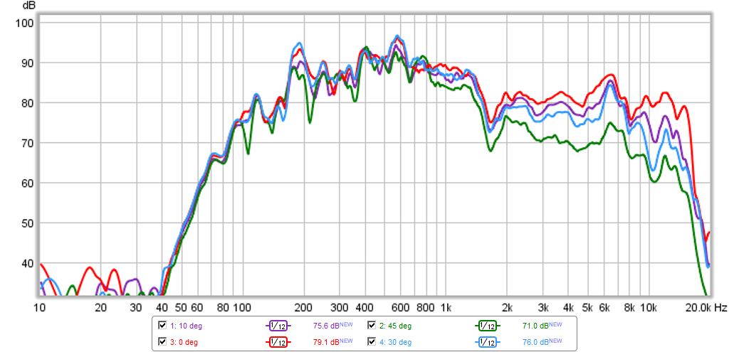
I made some more polar measurements right from the horn's mouth for later reference when the horns are finished. I don't know if horns should even be measured right from the mouth (or close in general) because of the possible reflections, but at least it minimizes room's effect to measurements. Some of the seen anomalies were not present in previous polar measurements and I suspect they are some horn wall reflections/cancellations or something like that.
Steps are approx. 2,75 deg horizontal and 2.25deg vertical (horn's coverage is approx. 55deg x 45deg). I covered the whole hor/vert coverage with 10-11 measurement points.
Solo JBL 2446J because that's where the action happens.
Horizontal, 10ms time window:
Horizontal sonogram, 10ms time window:
Vertical, 10ms time window:
Vertical sonogram, 10ms time window:
Steps are approx. 2,75 deg horizontal and 2.25deg vertical (horn's coverage is approx. 55deg x 45deg). I covered the whole hor/vert coverage with 10-11 measurement points.
Solo JBL 2446J because that's where the action happens.
An externally hosted image should be here but it was not working when we last tested it.
Horizontal, 10ms time window:
An externally hosted image should be here but it was not working when we last tested it.
Horizontal sonogram, 10ms time window:
An externally hosted image should be here but it was not working when we last tested it.
Vertical, 10ms time window:
An externally hosted image should be here but it was not working when we last tested it.
Vertical sonogram, 10ms time window:
An externally hosted image should be here but it was not working when we last tested it.
Last edited:
Legis,I made some more polar measurements right from the horn's mouth for later reference when the horns are finished. I don't know if horns should even be measured right from the mouth (or close in general) because of the possible reflections, but at least it minimizes room's effect to measurements.
For polar measurements to be valid, they must be done outside of the near-field boundary. In regard to full range frequency measurements, Pat Brown (who does measurements for DSL and others seeking impartial testing) wrote :
"A working “rule-of-thumb” for determining the boundary between near-field and far-field is to make the minimum measurement distance the longest dimension of the loudspeaker multiplied by 3.
He then writes:
"It is often thought that a remote measurement position is necessary for low frequencies since their wavelengths are long. Actually the opposite is true. It is more difficult to get into the far-field of a device at high frequencies, since the shorter wavelengths make the criteria in Item 4 more difficult to satisfy.
Item 4:
4. The distance from the source where the path length difference for wave arrivals from points on the device on the surface plane perpendicular to the point of observation are within one-quarter wavelength at the highest frequency of interest ."
This is an important distinction between high frequency and low frequency measurement, criteria #4 can be satisfied at 95 Hz for a subwoofer of one square meter measured at one meter. Your mid/high horn really needs a lot more distance to get valid results, which unfortunately would require testing outdoors at a distance from any boundaries to avoid their effects.
I'd expect if you measured at a distance, your polar plots would look more like the DSL SH 50, since your wall angles are similar.
Art
Attachments
Last edited:
Legis,
For polar measurements to be valid, they must be done outside of the near-field boundary.
[...]
Art
Thanks Art, that's really good info. I'll have to see measuring them outside at some point.
Legis,
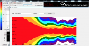
I finished my tractrix horn. Here are some polars with the old speaker's EQ so optimization still remains. Looks promising for 175Hz to 15kHz though.
More info here:
http://www.diyaudio.com/forums/full-range/259293-prv-5mr450-ndy-fast-applications-10.html#post4034668
I finished my tractrix horn. Here are some polars with the old speaker's EQ so optimization still remains. Looks promising for 175Hz to 15kHz though.
More info here:
http://www.diyaudio.com/forums/full-range/259293-prv-5mr450-ndy-fast-applications-10.html#post4034668
I had a revelation😀. I have a slight resonance at 3kHz. Covering the ports with a tape decrease this resonance. My injection port dia is approx. 11cm. 3khz wave lenght is 11,46cm😀. It is (can be) a standing wave inside the round port!
Need to test some startegically placed absorbing material inside the ports at some point.
Need to test some startegically placed absorbing material inside the ports at some point.
I had a revelation😀. I have a slight resonance at 3kHz. Covering the ports with a tape decrease this resonance. My injection port dia is approx. 11cm. 3khz wave lenght is 11,46cm😀. It is (can be) a standing wave inside the round port!
Need to test some startegically placed absorbing material inside the ports at some point.
I once filled the ports with foam, then found that the foam dramatically increased distortion 🙁
No free lunch...
The Anya array uses a fibonacci sequence for the midrange taps : http://www.diyaudio.com/forums/mult...-bandpass-mid-unity-horn-105.html#post3607500
I once filled the ports with foam, then found that the foam dramatically increased distortion 🙁
No free lunch...
The Anya array uses a fibonacci sequence for the midrange taps : http://www.diyaudio.com/forums/mult...-bandpass-mid-unity-horn-105.html#post3607500
I think even some 0,5cm thick lining inside the port could absorb the resonance quite much, that would not hinder the air flow in the port or cause distortion, I think. I'll see how it goes.
I will also round the corners and maybe use a router to cut some wood away from the other side of the ports to reduce the parallel wall area of the port. That should also reduce the resonance.
I'm starting to finish/paint the horns tomorrow. 🙂
I was using 3" woofers, so velocity becomes an issue with my horns
I found that reticulated foam didn't increase distortion much, but it also didn't improve the frequency response much either
Closed cell foam improved response, but also increased distortion
Kef uses closed cell foam in their ports (check out the LS50 from Kef)
something like this...I will also round the corners and maybe use a router to cut some wood away from the other side of the ports to reduce the parallel wall area of the port. That should also reduce the resonance.

^Something along those lines yes. I have to go and buy a 45deg router piece for that.
Dividing the port to two identical halfs did nothing to the resonance. So it's not a standing wave inside the port, just coincidence?
Placing a foam onto the closer side of the port reduced the resonance a bit. Funnily on the outer edge (further side of the port from the apex) the foam did nothing! So it's related to the impedance matching of the port's first edge closer to the apex, or diffraction, or both? Foam both increased the impedance of the port (flare's change seems little less abrupt) and attenuated diffractions so it's hard to tell.
Maybe I coould also round, just slightly, the inside edges of the ports to reduce possible diffractions from those edges? maybe the comp would also like it, less abrupt change in horn's flare?
Dividing the port to two identical halfs did nothing to the resonance. So it's not a standing wave inside the port, just coincidence?
Placing a foam onto the closer side of the port reduced the resonance a bit. Funnily on the outer edge (further side of the port from the apex) the foam did nothing! So it's related to the impedance matching of the port's first edge closer to the apex, or diffraction, or both? Foam both increased the impedance of the port (flare's change seems little less abrupt) and attenuated diffractions so it's hard to tell.
An externally hosted image should be here but it was not working when we last tested it.
Maybe I coould also round, just slightly, the inside edges of the ports to reduce possible diffractions from those edges? maybe the comp would also like it, less abrupt change in horn's flare?
Last edited:
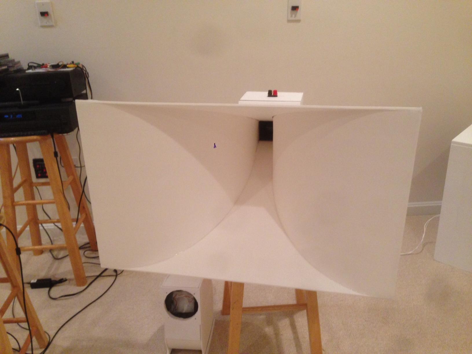
Took the first synergy apart for and measured the halfway runned in Deltalite 2515 at 1m free air like shown in the picture. Curvilinear cone rocks.
An externally hosted image should be here but it was not working when we last tested it.
An externally hosted image should be here but it was not working when we last tested it.
An externally hosted image should be here but it was not working when we last tested it.
An externally hosted image should be here but it was not working when we last tested it.
Last edited:
Legis,Dividing the port to two identical halfs did nothing to the resonance. So it's not a standing wave inside the port, just coincidence?
Placing a foam onto the closer side of the port reduced the resonance a bit. Funnily on the outer edge (further side of the port from the apex) the foam did nothing! So it's related to the impedance matching of the port's first edge closer to the apex, or diffraction, or both?
The throat entrance area is likely the major cause of the resonance (and diffraction), not the ports. Unfortunately, to properly fix the problem would require a major re-build, the apex of the horn should be less than 2" square, then fared (using rounded files) out to make a smooth round to rectangular transition. Filling in the gap won't provide a conical expansion, so that area of the horn will have problems, as you could see when comparing HF response prior to cutting the port holes in to after.
Art
Attachments
Legis,
The throat entrance area is likely the major cause of the resonance (and diffraction), not the ports. Unfortunately, to properly fix the problem would require a major re-build, the apex of the horn should be less than 2" square, then fared (using rounded files) out to make a smooth round to rectangular transition. Filling in the gap won't provide a conical expansion, so that area of the horn will have problems, as you could see when comparing HF response prior to cutting the port holes in to after.
Art
Hi Art, this is (hopefully) the case. I also measured better behaviour with the preliminary transiotion smoothing I did back then.
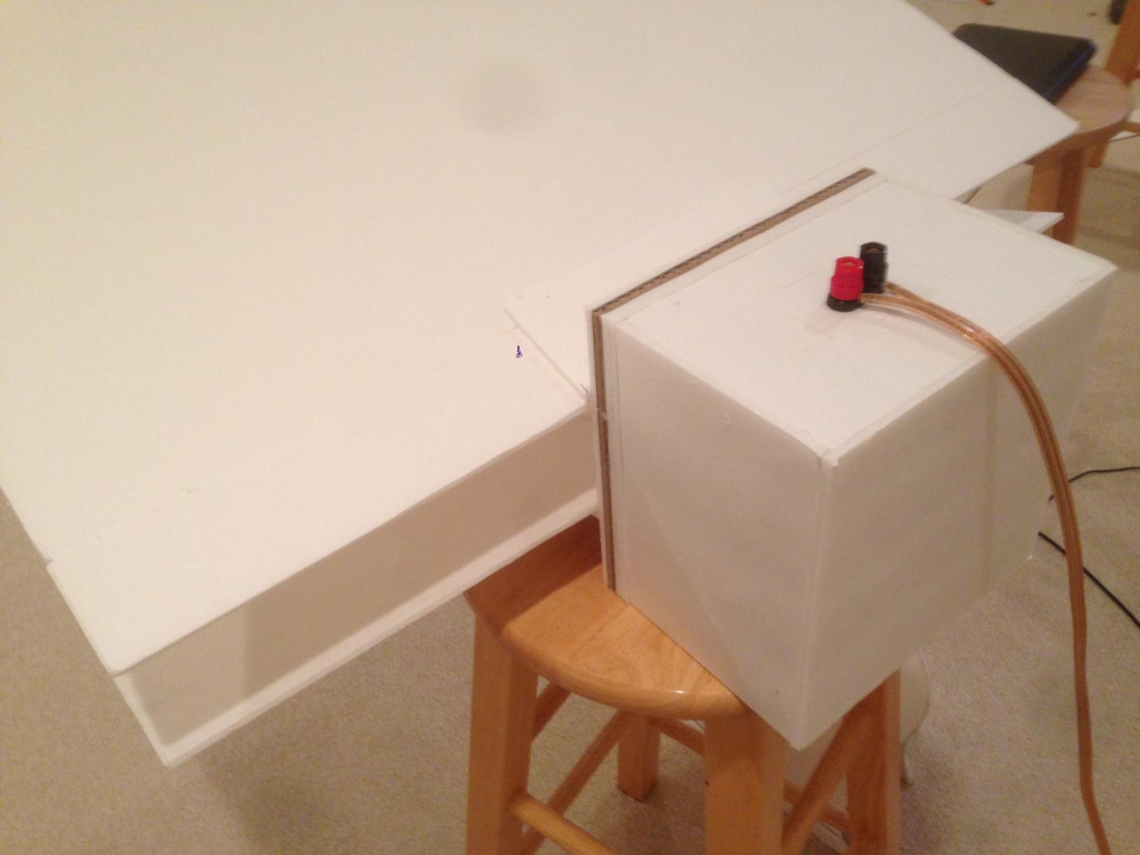
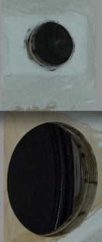
Here's a picture of the second (undried) transition treatment. With enough repetition and patience I try to land somewhere near smooth and linear expansion. I hope it does not screw up the sound I already got out from these 😀.
An externally hosted image should be here but it was not working when we last tested it.
I also rounded the mouh of the horn yesterday and treated the injection ports. Have to use knife where the router could not fit.
An externally hosted image should be here but it was not working when we last tested it.
An externally hosted image should be here but it was not working when we last tested it.
An externally hosted image should be here but it was not working when we last tested it.
Also did some testing with the RAL 3001 -colored speaker cabinet paint.
An externally hosted image should be here but it was not working when we last tested it.
Third throat treatment. Already starting to feel like a smooth transition, but not the most linear/conical yet.
An externally hosted image should be here but it was not working when we last tested it.
It can never be anything but a parabolic (or whatever shape you choose) transition to conical, unless you rebuild the horn, extending it to the driver exit dimension so the horn starts and stays conical.Third throat treatment. Already starting to feel like a smooth transition, but not the most linear/conical yet.
Last edited:
I see what you are saying Weltersys, the best wY to fix is to extend the vertex end farther back so that the CD throat starts at a smaller area and avoids the jump to the rectangular area discontinuity. Build a small piece to extend back may be best option.
- Status
- Not open for further replies.
- Home
- Loudspeakers
- Subwoofers
- Study of a Dipole/Cardioid Bass Horn