good sir i am interested in this pcb.....another PCB for Sankens , have split Q7 from Q8 ....😉
and I need to check somebody if it's OK , and then I will post layout in black and white and the rest of files .🙂
Regards ,Alex
Regards
I understand .. I just try to help you ...
Regards,
Marcel
Hi Marcel,
I see you use photo etching. I believe that produces a much better results than iron transfer. I have contemplated trying that but the cost of the boards always deters me. I actually built a UV light board but just haven't pulled the plug on buying all the other stuff required for photo etching. I may still try that some day if I can find a good supplier.
Hi Valery,
I have been playing around with the spice file this morning but to be honest the THD doesn't look all that good compared to most of my other amps. The AX14 sims a lot better.
Blessings, Terry
.....another PCB for Sankens , have split Q7 from Q8 ....😉
and I need to check somebody if it's OK , and then I will post layout in black and white and the rest of files .🙂
Regards ,Alex
Hi Alex,
- Good idea Q7, Q8 and Q9 can be attached to a piece of plate.
- Better 3 pairs Sanken so the board can be replaced 3 pairs Toshiba
- Addition of board length will reduce the width of the board or <80 mm
- As the board design on the B500 and H900 are very beautiful.
I am Sorry if my request is too excessive.
Regards,
Yassud
Sir mile thank you so much sir, Sir thimios and sir alex thank you so much...god bless you all....🙂
I LIKE THIS AMP.😀 THANKS SIR MILE AND SIR ALEX..😱
Attachments
I LIKE THIS AMP.😀 THANKS SIR MILE AND SIR ALEX..😱
Nice work,
Regards
Nice work,
Regards
thank you so much sir Mile, more power god bless you always ...🙂
Hi Guys,
I see some of you have working models so this amp must work but I am struggling to get mine going. I'm not getting any signal through to the output. As a matter of fact I have too much interference on the input to even get a clean reading on the scope there. I'm using an NTE 941M for the servo and that may be part of the problem I'm not sure. I tried building a spice model but it is showing as bad of results as I am getting from my amp. I am attaching the spice model and Cordell models. If one of you who knows ltspice could take a look, maybe you can find the issue. I would like to get it working so I can use it to trouble shoot my boards.
I built the amp from the foil pattern in post 1625. There are two 100n caps on the board that are not in the schematic. I added those to the spice model. Any help appreciated.
Blessings, Terry
When such a thing happened to me, I used a single strand copper wire and jumped it end to end on the tracks, soldering on the turns. The big copper pad may be open as it has so many holes.
gajanan phadte
I have checked continuity throughout the board. I can't find any open circuits yet I have some very strange readings especially around the vas. I have the same issues on both boards which makes me suspect the layout. I have some better boards so I may try etching a new board and trying one more time. I hate giving up on things but this one is tempting me.
I have checked continuity throughout the board. I can't find any open circuits yet I have some very strange readings especially around the vas. I have the same issues on both boards which makes me suspect the layout. I have some better boards so I may try etching a new board and trying one more time. I hate giving up on things but this one is tempting me.
Please post your voltage measurements.
Hi Miles,
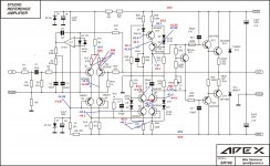
I am attaching a schematic with voltages. Voltages in blue are what Ltspice says I should see. Red are the actual voltages that I read.
Thanks, Terry
Edit: As you can see I have no voltage drop across R24. However, measuring across it in circuit I see 6.9K. I have checked and I don't have any shorts so I'm not sure how that voltage is getting around it..
Attachments
Last edited:
Hi Miles,
I am attaching a schematic with voltages. Voltages in blue are what Ltspice says I should see. Red are the actual voltages that I read.
Thanks, Terry
Edit: As you can see I have no voltage drop across R24. However, measuring across it in circuit I see 6.9K. I have checked and I don't have any shorts so I'm not sure how that voltage is getting around it..
Measure voltage on zener D2 must be 15V. LTP current is to low (500uA instead 1mA) and there is no any current thru the VAS...
Sorry I thought I included that voltage. The zeners are between 14.6 and 15V I see that the LTP is low and Q7 and Q8 have almost no vbe. I just don't understand why. I have checked all of the values and they are per the schematic. All of the suspect devices were replaced even though they measured good. Still the same result.
Hi Terry, is it possible, Q7 is soldered the wrong way?
With MJE340/350 it's easy - collector is in the middle and if you turn it 180 degrees by mistake, you swap B and E. This may be the reason why you don't have current through R24 (Q7 is completely "off" because of reversed Vbe).
Cheers,
Valery
With MJE340/350 it's easy - collector is in the middle and if you turn it 180 degrees by mistake, you swap B and E. This may be the reason why you don't have current through R24 (Q7 is completely "off" because of reversed Vbe).
Cheers,
Valery
Did you see the Vbe of Q9.Hi Miles,
I am attaching a schematic with voltages. Voltages in blue are what Ltspice says I should see. Red are the actual voltages that I read.
Thanks, Terry
Edit: As you can see I have no voltage drop across R24. However, measuring across it in circuit I see 6.9K. I have checked and I don't have any shorts so I'm not sure how that voltage is getting around it..
Does that raise a red flag?
This version did not work well sir I am very interested in this version?.....another PCB for Sankens , have split Q7 from Q8 ....😉
and I need to check somebody if it's OK , and then I will post layout in black and white and the rest of files .🙂
Regards ,Alex
Regards
Hi Valery,Hi Terry, is it possible, Q7 is soldered the wrong way?
With MJE340/350 it's easy - collector is in the middle and if you turn it 180 degrees by mistake, you swap B and E. This may be the reason why you don't have current through R24 (Q7 is completely "off" because of reversed Vbe).
Cheers,
Valery
I used the layout from post 1625. I have all three MJE on a common heat sink those devices have exposed metal on the mating surface. Very clear which direction they face. They are mounted correctly and insulated, I checked closely.
What is the voltage measured at R14 each end.[\QUOTE]close to zero each end.there is a servo.
Yes, there are several red flags. The voltages around the 4, 1N4148 all look wrong but they are mounted per the layout and measures good with the DMM set on diode test' yet there is no voltage drop to the base of Q8. very strange.Did you see the Vbe of Q9.
Does that raise a red flag?
Something is terribly wrong. Broken transistors?
I mean, some voltages are totally unrealistic, assuming the actual build is in sync with schematic... it's either not, or some active elements (Q5-Q10) show inadequate behavior by some reason...
I mean, some voltages are totally unrealistic, assuming the actual build is in sync with schematic... it's either not, or some active elements (Q5-Q10) show inadequate behavior by some reason...
- Home
- Amplifiers
- Solid State
- Studio Reference Amplifier