oh sad story, i got blown OP and smoked RC network..feel like a parasitic oscillation is happening :-(
update: I found the caulprit, it's my mistake anyway. An ungrounded heatsink in KSE350 which is act like an antenna, now it fixed properly.
update: I found the caulprit, it's my mistake anyway. An ungrounded heatsink in KSE350 which is act like an antenna, now it fixed properly.
Can you post picture close up to all component...
Last edited:
Hi Wil,
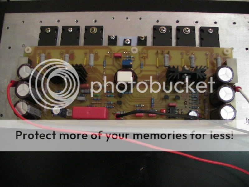
Here you go.
Other channel is rock solid except this one, I might change all output tranny.
Thanks,
Junie
Last edited:
Hi Wil,
Here you go.
Other channel is rock solid except this one, I might change all output tranny.
Thanks,
Junie
Hi Jun,
Opss.. sad to hear that bro, i suggest to double check and confirm first before replacing don't waste.. they aren't cheap tranies.
Did you use any replacement? I suggest to do actual test vs. schematic before solder specially replacement tranies.
FYI only, in Middle East i encounter lots of tranies have different pin orrientation as per original data sheet so better to do actual test before solder.
Regards,
Wiljj78
Last edited:
Yes Wil,
Will do that, but surely oscillation is happening, i can say that because if i touch the heatsink of KSE350 the light bulb is glowing a bit, soething is wrong in that section. Will tackle this issue later, I will keep you posted.
Cheers,
Junie
Will do that, but surely oscillation is happening, i can say that because if i touch the heatsink of KSE350 the light bulb is glowing a bit, soething is wrong in that section. Will tackle this issue later, I will keep you posted.
Cheers,
Junie
Yes Wil,
Will do that, but surely oscillation is happening, i can say that because if i touch the heatsink of KSE350 the light bulb is glowing a bit, soething is wrong in that section. Will tackle this issue later, I will keep you posted.
Cheers,
Junie
Hi June,
I hope you insulate your rear metal case of both Q7&Q8 MJE340 or KSE350 against heatsink, sometime shorted may occur on collector to heatsink which it shouldn't be.
these type of transistors doesn't have a metal tab behind, it's all encapsulated in plastic package but something is picking up a frequency from that area i reckon.
these type of transistors doesn't have a metal tab behind, it's all encapsulated in plastic package but something is picking up a frequency from that area i reckon.
Connect 5-10pF from colector Q9 (MJE350) to base Q2 (BC560) for compensation.
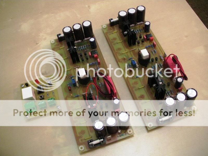
it's all working now
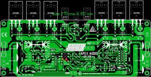
Ok here's what i found, in the schematic below the 100pF(enclosed in red) is not included in Alex's PCB version 3.1.
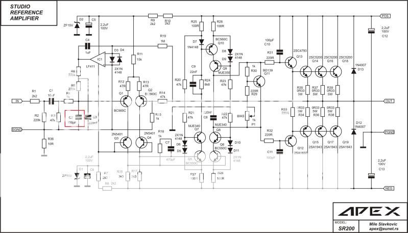
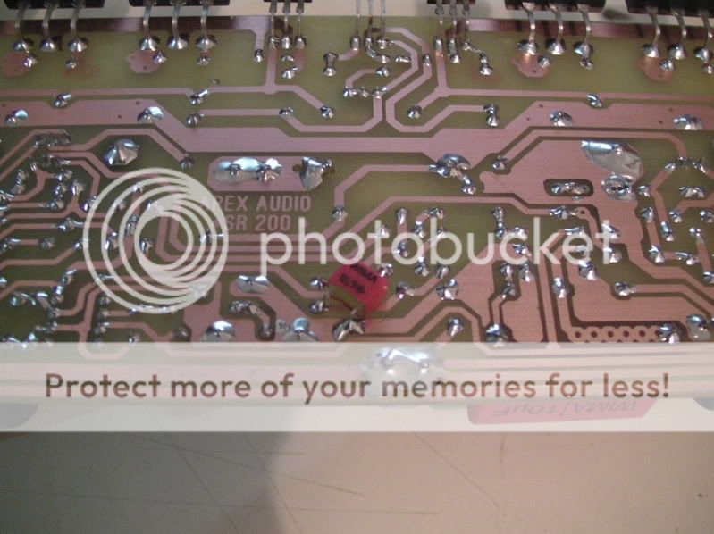
With the inclusion in my build it removes that unwanted oscillation, noticed how did i solder in the back of the PCB.
Ok here's what i found, in the schematic below the 100pF(enclosed in red) is not included in Alex's PCB version 3.1.
With the inclusion in my build it removes that unwanted oscillation, noticed how did i solder in the back of the PCB.
I see new pcb of Sr200 has Trimmer resistor, I suppose for setting Bias, what Audible difference is it making to audio quality.
Ugh, Darlington for the output stages. You'd do far better using Sziklai pairs for the output, more linear and you get better output swing.
@Junie....did you notice the zobel circuit missing in the o/p end of the amp? a 10 ohm and 100n would do the job...
Hello Amptech,
In the final PCB Alex include it (enclosed in red), please see below photo.
 .
.
Actually my approach on finding the fault is from OP backward but I noticed that whenever I touch components in the input stage the buzzing sound is there and the Light bulb is glowing happily, double checked the schematic and found the cap(100pF) is missing.
Cheers,
Junie
In the final PCB Alex include it (enclosed in red), please see below photo.
Actually my approach on finding the fault is from OP backward but I noticed that whenever I touch components in the input stage the buzzing sound is there and the Light bulb is glowing happily, double checked the schematic and found the cap(100pF) is missing.
Cheers,
Junie
Ok here's what i found, in the schematic below the 100pF(enclosed in red) is not included in Alex's PCB version 3.1.
With the inclusion in my build it removes that unwanted oscillation, noticed how did i solder in the back of the PCB.
Congrats....and thanks for sharing.

Which version is working fine??
Regards,
:

Ok here's what i found, in the schematic below the 100pF(enclosed in red) is not included in Alex's PCB version 3.1.
With the inclusion in my build it removes that unwanted oscillation, noticed how did i solder in the back of the PCB.
DC protector for B500
Mr. mile DC surge protector is whether it can be used for the B500?
Regard 🙂
Schematic of Speaker Terminal.
Mr. mile DC surge protector is whether it can be used for the B500?
Regard 🙂
DC protector for B500
Mr. mile DC surge protector is whether it can be used for the B500?
Regard 🙂
Schematic of Speaker Terminal.
Mr. mile DC surge protector is whether it can be used for the B500?
Regard 🙂
- Home
- Amplifiers
- Solid State
- Studio Reference Amplifier