I apologize for this.
V from base to ground Q2=-10mV
V across R14(feedback res.)=100mV.
Sorry for this.🙁
What is voltages measurement on R34 and R35?
Zobel value in uH
V base Q2 to ground = 63mV
V on R14 = 59,6mV
check this http://www.diyaudio.com/forums/solid-state/173462-studio-reference-amplifier-77.html
that because not grounded heatsink & missing cap...
Thimios, do you use small heat sink for all MJE transistor & grounded the heat sink?
they are warm(maybe hot) on +/-45VDC
I want to know the inductor value (in uH) & what happen when we increase or decrease the value?
because I got smoke on resistor zobel today (resistor series with 100nF to ground).
I use speaker terminal that was use on AX14, maybe because of that?
The resistor smoked when I unplug the speakers & with "loop" cable from input to ground.
I check again my SR200, now in cold heatsink... DC offset is 0,..mVI apologize for this.
V from base to ground Q2=-10mV
V across R14(feedback res.)=100mV.
Sorry for this.🙁
V base Q2 to ground = 63mV
V on R14 = 59,6mV
check this http://www.diyaudio.com/forums/solid-state/173462-studio-reference-amplifier-77.html
that because not grounded heatsink & missing cap...
Thimios, do you use small heat sink for all MJE transistor & grounded the heat sink?
they are warm(maybe hot) on +/-45VDC
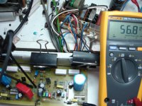
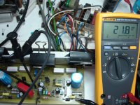
Hi Mr Mile,What is voltages measurement on R34 and R35?
I want to know the inductor value (in uH) & what happen when we increase or decrease the value?
because I got smoke on resistor zobel today (resistor series with 100nF to ground).
I use speaker terminal that was use on AX14, maybe because of that?
The resistor smoked when I unplug the speakers & with "loop" cable from input to ground.
No, I use standard from Apex's schematic no changes... I will try that to solve my oscillation problem
I changed R24 to 2W & C 9 to 250V, high voltage there
Add 18pf capacitor or similar connected from collector Q9 to base Q2 to solve oscillation problem, inductor on speaker terminal is about 1uH.
Regards
John and Thim,
My annual leave will start tomorrow, I will join in your adventure with SR200 😀.
BR,
Junie
My annual leave will start tomorrow, I will join in your adventure with SR200 😀.
BR,
Junie
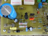
sr200 studio refer.
V across R34=30mV
V across R35=30mv
Welcome Mr Mile!🙂What is voltages measurement on R34 and R35?
V across R34=30mV
V across R35=30mv
sr200 studio refer.
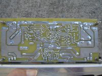
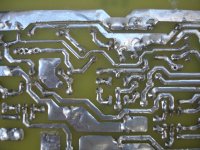
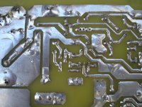
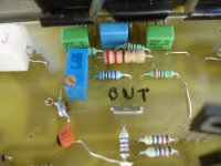
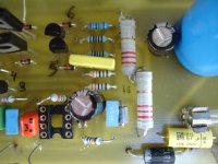
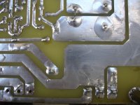
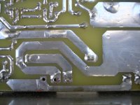
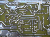
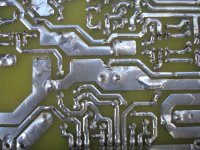
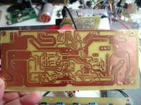
Some photos from serial🙂
Some photos from serial🙂
Attachments
-
 DSC06656.JPG592.2 KB · Views: 1,210
 -
 DSC06665.JPG565.6 KB · Views: 159
 -
 DSC06664.JPG551.8 KB · Views: 166
 -
 DSC06663.JPG605.1 KB · Views: 194
 -
 DSC06662.JPG610.2 KB · Views: 210
 -
 DSC06661.JPG531.4 KB · Views: 213
 -
 DSC06660.JPG552.5 KB · Views: 879
 -
 DSC06659.JPG585.9 KB · Views: 940
 -
 DSC06658.JPG588.8 KB · Views: 1,008
 -
 DSC06657.JPG604.4 KB · Views: 1,109
sr200 studio refer.
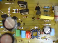
others
others
Attachments
-
 DSC06655.JPG588.4 KB · Views: 187
 -
 DSC06654.JPG571.5 KB · Views: 186
 -
 DSC06672.JPG552.3 KB · Views: 90
 -
 DSC06671.JPG594.2 KB · Views: 79
 -
 DSC06670.JPG570.5 KB · Views: 86
 -
 DSC06669.JPG581.6 KB · Views: 94
 -
 DSC06668.JPG601.1 KB · Views: 108
 -
 DSC06667.JPG537.2 KB · Views: 117
 -
 DSC06666.JPG591.2 KB · Views: 150
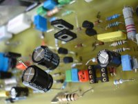
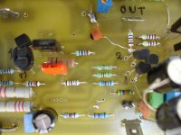
From the photos I can see no heat sink on your MJE's!!!
They are quite warm when I tested, in my mine they are with little heat sink...
Maybe that cause your problem, please try put little heat sink on them, with insulator for safety!
I guess the more heat the more unstable they are...
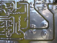
BTW bottom side just look similar to my build
They are quite warm when I tested, in my mine they are with little heat sink...
Maybe that cause your problem, please try put little heat sink on them, with insulator for safety!
I guess the more heat the more unstable they are...
BTW bottom side just look similar to my build
Mje are quiet cool under test conditions.From the photos I can see no heat sink on your MJE's!!!
They are quite warm when I tested, in my mine they are with little heat sink...
Maybe that cause your problem, please try put little heat sink on them, with insulator for safety!
I guess the more heat the more unstable they are...
BTW bottom side just look similar to my build
At first test mje has small heatshing on it.
Has removed this later for more comfortable test.
No the problem isn't here.
This pcb isn't same to your's
This pcb is Sanken vers. by Alex mm and i don't know if this is tested.
I examine this point to point but i can't see faults.
See here http://www.diyaudio.com/forums/solid-state/173462-studio-reference-amplifier-115.html post #1148 for your problem
In that post you can see the small heatshings on mje transistors.
Last edited:
Thim,
I saw your earlier post that sine wave totally good, I'm jealous cause I don't have scope.
Why you afraid what square wave tell you, better is to let your ears tell you the sound
this some suggestion make it proper case, proper power supply, proper ground etc...
and tell us again the story after you finish it.
Actually I want to start again my last year SR200 that not finish yet... yes it is more than one year 😀
that time I feel not ready yet to finish it
but know I have better parts... but no transformer yet (I will build one special for it)
I will use 3 pairs of sanken just like yours, tomorrow I will post some picture 🙂
I need to know may I call it SR300 😀
I apologize for this.
V from base to ground Q2=-10mV
V across R14(feedback res.)=100mV.
Sorry for this.🙁
Can't find error on pictures. 1.15mA R14, 0.53mA R17, 0.6mA leaks somewhere. I think you should measure currents on R14 to R17 path to find where it leaks. Collector currents Q2 and Q4 at first.
Can't find error on pictures. 1.15mA R14, 0.53mA R17, 0.6mA leaks somewhere. I think you should measure currents on R14 to R17 path to find where it leaks. Collector currents Q2 and Q4 at first.
1.15mA R14 ?
Propably you mean R13.
Thanks for replay.
Last edited:
1.15mA R14 ?
Propably you mean R13.
Thanks for replay.
Yes, it's R13 not R14. Sorry.
@Bli John Widhi...Aha you finally found the problem...
I will modify my SR200 later...as Mr. Mile S. suggested.
Grounding MJEs HS, resistor value changes and 10pf caps are the hot issue here...I have no 18pf caps in my drawer, may I use 20pf? or just put 10pf as compensation caps?
Thank you so much...
Best Regards...
I will modify my SR200 later...as Mr. Mile S. suggested.
Grounding MJEs HS, resistor value changes and 10pf caps are the hot issue here...I have no 18pf caps in my drawer, may I use 20pf? or just put 10pf as compensation caps?
Thank you so much...
Best Regards...
sr200 studio refer.
Thanks tinitus🙂
Hoping for help....from anywhere
My bad English😛thimios, sorry if its OT, but when you write replay, do you mean reply ?
Thanks tinitus🙂
Hoping for help....from anywhere
Last edited:
@Bli John Widhi...Aha you finally found the problem...
I will modify my SR200 later...as Mr. Mile S. suggested.
Grounding MJEs HS, resistor value changes and 10pf caps are the hot issue here...I have no 18pf caps in my drawer, may I use 20pf? or just put 10pf as compensation caps?
Thank you so much...
Best Regards...
Hi mas Arif,
connecting in series your 20pf, you have 10pf
- Home
- Amplifiers
- Solid State
- Studio Reference Amplifier