checking as in 'measured', and not 'just' by looking at color codes ?
or else, measure a similar spare component/resistor, and compare color codes with the ones mounted
just checking
R12,R13 =47R/+-1% MEASURED an color code checking.
kirchhoff say I(R11)=I(R12)+I(R13)

1.65mA=0.51mA+1.14mA
V(R11)=0.00165*8200=13.53V Measurment on R11=13.8v

Last edited:
R12,R13 =47R/+-1% MEASURED an color code checking.
kirchhoff say I(R11)=I(R12)+I(R13)
1.65mA=0.51mA+1.14mA
V(R11)=0.00165*8200=13.53V Measurment on R11=13.8v
Just asking, is there 2x470uF capacitor on it's place?
Just asking, is there 2x470uF capacitor on it's place?
In series with R15
Thanks for replay.
Attachments
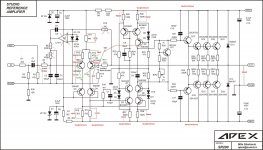
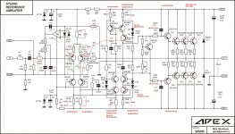
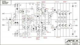
sr200 studio refer.
I would ask anyone has built this amp to measure VR12,VR13.Just two measurments without putting servo out.🙂
I would ask anyone has built this amp to measure VR12,VR13.Just two measurments without putting servo out.🙂
Hi Thimios, I've build it too but not finish yet waiting for transformer to use... what voltage do you use it without servo? I will check my SR200 too so you can compare to it...
resistor checked, input LTP Vbe checked.
There is still serious imbalance in the LTP.
Now check the Vbe of the mirrors and the VAS.
There is still serious imbalance in the LTP.
Now check the Vbe of the mirrors and the VAS.
sr200 studio refer.
Keep in mind that amplifier is functional .
Thanks for replay.
good luck.🙂
I use +/-45V with and without servo.Hi Thimios, I've build it too but not finish yet waiting for transformer to use... what voltage do you use it without servo? I will check my SR200 too so you can compare to it...
Keep in mind that amplifier is functional .
Thanks for replay.
good luck.🙂
Tkanks Mr, Andrew .resistor checked, input LTP Vbe checked.
There is still serious imbalance in the LTP.
Now check the Vbe of the mirrors and the VAS.
I can check this as soon as i can.
sr200 studio refer.
Hi Mr Andrew
Here are measurments.
Hi Mr Andrew
Here are measurments.
Attachments
Last edited:
sr200 studio refer.
Ok here again.None of those are broken. But too much variation.
Now do Q5, 6, 10 & it's partner.
Attachments
Ok here again.
0mV on base Q2 vs gnd looks impossible, please measure it again and check for errors. Anyway, if it works ok why bother?
sr200 studio refer.
I try to remove servo .
Apex say .....without servo and with unmatched LTP transistors the expected
offset is about +/-10mV.
In mine case offset without servo is 100mV with matched transistors
Thanks for replay.
0mV on base Q2 vs gnd looks impossible, please measure it again and check for errors. Anyway, if it works ok why bother?
I try to remove servo .
Apex say .....without servo and with unmatched LTP transistors the expected
offset is about +/-10mV.
In mine case offset without servo is 100mV with matched transistors
Thanks for replay.
Last edited:
I try to remove servo .
Apex say .....without servo and with unmatched LTP transistors the expected
offset is about +/-10mV.
In mine case offset without servo is 100mV with matched transistors
Thanks for replay.
Suppose output offset is +100mV. Left pin R14 is lower potential and current flows where? Capacitor blocks it from R15, and reverse base-emitter Q2 blocks it there. Even more weird, 54mV R13 suggest counter current. If measurements are not accurate, maybe problem is not accurate too?
Suppose output offset is +100mV. Left pin R14 is lower potential and current flows where? Capacitor blocks it from R15, and reverse base-emitter Q2 blocks it there. Even more weird, 54mV R13 suggest counter current. If measurements are not accurate, maybe problem is not accurate too?
And if suppose -100mV output offset, R13 is prime suspect. Look for some short circuits on layout, R13 to emitter Q2 connection.
Hi Thimios,I try to remove servo .
Apex say .....without servo and with unmatched LTP transistors the expected
offset is about +/-10mV.
In mine case offset without servo is 100mV with matched transistors
Thanks for replay.
this what I got:
with servo & rail +/-43V
R11 =14,96V (15,59V on the zener)
R12 = 23,3mV
R13 = 23,6mV
R16 = 1,531V
R17 = 1,548V
R25 = 880mV
R26 = 856mV
R27 = 860mV
R28 = 882mV
DCO = 0.1mV (with TL071)
without servo anything not changed to much only DCO = 1,6mV 😉
(I only lift R5 & add a bipolar cap on R15 see attachment)
I try to match all transistor to it partner, they are closely matched
that why I get very small DCO when servo is disconnected
I have my own problem, when I connect input to ground with cable I have smoke on the zobel resistor without speaker connected.
When the speaker connected it all okay but when I disconnect that happen...
Now I must find what wrong with this 😱 btw maybe because the cable is to long
Attachments
Last edited:
sr200 studio refer.
Thanks for all.
Now it's clear that it's my problem.
I have a another qwestion .Is any 18pf capacitor or similar connected from collector Q9 to bace Q2 in your amplifier?
Thanks for all.
Now it's clear that it's my problem.
I have a another qwestion .Is any 18pf capacitor or similar connected from collector Q9 to bace Q2 in your amplifier?
No, I use standard from Apex's schematic no changes... I will try that to solve my oscillation problem
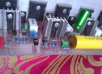
I changed R24 to 2W & C 9 to 250V, high voltage there
I changed R24 to 2W & C 9 to 250V, high voltage there
Last edited:
No, I use standard from Apex's schematic no changes... I will try that to solve my oscillation problem
I changed R24 to 2W & C 9 to 250V, high voltage there
If you have see all posts Apex suggest to me this modification because there is an overshoot .
I must try to remove this again
I apologize for this.0mV on base Q2 vs gnd looks impossible, please measure it again and check for errors. Anyway, if it works ok why bother?
V from base to ground Q2=-10mV
V across R14(feedback res.)=100mV.
Sorry for this.🙁
Attachments
Last edited:
- Home
- Amplifiers
- Solid State
- Studio Reference Amplifier