If you have a 5V power bank try powering MCU and mic with that.Meanwell power supply is connected to the strips and to the microcontroller.
i don't have a real powerbank. i have a jbl chargeplus bluetooth speaker. but with it you can also charge devices. but then the noise is bigger and the leds are no longer controlled correctly.If you have a 5V power bank try powering MCU and mic with that.
I have described my problems in parallel times in the Ti forum:
Hi,
Although I can't really solve any noise issues for you, I have a few comments that might contribute to the noises you are seeing.
- I see you are running 4 SPI modules at 4.8Mhz. This can create SSO (simultaneous switching output) which can draw quite some currents and affects the voltage supply. Proper decoupling caps and placement of them is critical for high speed operations.
#define SSI_CLOCK (4800000)
- You are using the LaunchPad board. The LaunchPad has VDDA for ADC tied to VDD for simplicity. In another word, any noise on the digital supply can couple to the analog supply for ADC which will affect ADC accuracy. If you were to design your own board, I will suggest you split the supplies to digital and analog domains. ADC VREFP and VREFN are connected to VDDA and GNDA internally. Any noises or ripples on the VDD/GND will follow VREF and hence the accuracy.
- I see you use CH5 for ADC. If you are willing to do an experiment you can try a different ADC channel perhaps with the pin that is far away from the SSI modules or reduce the SSI_CLOCK speed to see if it alleviates your finding. Other than that, I have not much left to offer.
MAP_ADCSequenceStepConfigure(ADC0_BASE, 3, 0, ADC_CTL_CH5 | ADC_CTL_IE |
ADC_CTL_END);
When you create your own design, please go through section 4.5 for ADC design considerations as well as the rest of the document for best design practices.
Lowering SSI clock speed makes sense.
My recommendation is to use Mean Well only for LEDs. Instead of power bank do you any other 5V supply to power MCU and mic? And if you power MCU and mic from lab supply and LEDs from Mean Well do you still have noise?
My recommendation is to use Mean Well only for LEDs. Instead of power bank do you any other 5V supply to power MCU and mic? And if you power MCU and mic from lab supply and LEDs from Mean Well do you still have noise?
i have to order it.Instead of power bank do you any other 5V supply to power MCU and mic?
I try it but i the leds are going crazy.And if you power MCU and mic from lab supply and LEDs from Mean Well do you still have noise?
Did you tie 0V from both supplies together?I try it but i the leds are going crazy.
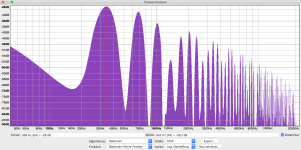
I have just tested it. it makes hardly any difference if I send with only one SSI or with 2 or with 3 or with 4. the noise is already present with one data transfer and is amplified by each further data transfer by approx. 5-6dB.Lowering SSI clock speed makes sense.
i will test it laterDid you tie 0V from both supplies together?
If you power the LEDs and MCU+mic with 2 separate supplies that are floating (i.e. 0V not tied together) I would not expect your setup to work. The result will be random LED control and extra noise.
i will try everything what it comes from you.Assuming the crosstalk comes from the LED strip's ground current, this would be one way to lay the wiring out. Star connection at the supply to minimize the mutual impedance, twisting to avoid magnetic coupling as much as possible, capacitor reduces efficacy of the star connection, but provides a return path for the data signal close to the data wire. Value of the capacitor to be determined experimentally, you could try 0, 1 nF and 100 nF to get an idea what works best.
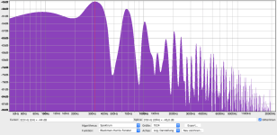
I have changed the wiring according to your instructions
The noise goes down to an rms value of -40dB.
good, but not enough for my application.
what else can i do to improve it?
I would like to correct again.
after these changes but also before:
the noise is only there during a transmission of data over spi.
it does not matter whether the data lines are connected or not.
it doesn't matter where the mcu is connected, the noise will still be transmitted through the different power supplies.
Attachments
Last edited:
If you have noise when data is transmitted over SPI regardless if data lines are connected or not it seems that the board 3.3V cannot be used for mics. I would try a separate low noise supply for the mics.
What microphone and preamplifier board do you use at the moment? If it is something with an electret microphone, can you replace the resistor that supplies it with two resistors in series and an electrolytical capacitor from the node that connects them to ground?
In post #69 the MCU board appears to be powered through USB micro cable. What is that connected to?
I just did that again with the lab power supply. but how do I disconnect the two power supplies so that the noise is not transmitted to the microphone. because as soon as I connect the two GND. the noise is there again.I would try a separate low noise supply for the mics.
I have two do choise, what is the best:What microphone and preamplifier board do you use at the moment?
1. Analog MEMS Mikrofon ICS-40180
https://www.sparkfun.com/products/18011
2. Analog electret microphone Maxim MAX4466
https://www.adafruit.com/product/1063
yes i can do this, but i dont understand it what is to do.If it is something with an electret microphone, can you replace the resistor that supplies it with two resistors in series and an electrolytical capacitor from the node that connects them to ground?
one for the power connection and one for programmingIn post #69 the MCU board appears to be powered through USB micro cable. What is that connected to?
https://github.com/adafruit/Adafruit-MAX4466-Electret-Mic-Amplifier-PCBsIs there a schematic for the Afafruit MAX4466 module somewhere?
PCB files for Adafruit MAX4466 Electret Mic Amplifier. The format is EagleCAD schematic and board layout
Yes, but what power supply?one for the power connection and one for programming
Do you see this noise with scope or with your soundcard?I just did that again with the lab power supply. but how do I disconnect the two power supplies so that the noise is not transmitted to the microphone. because as soon as I connect the two GND. the noise is there again.
meanwell power supplyes, but what power supply?
Do you see this noise with scope or with your soundcard?
with the soundcard
I have another EK-TM4C123GXL.
If I use one board for the SPI transmission and the other for the recording of the samples. Can I then separate both boards from one another so that the noise is not transmitted?
But I need a data interface between the boards. So that I can transfer data. And I need between the boards 3-5 GPIO ports as input or output.
- Home
- Design & Build
- Construction Tips
- Strong noise floor when the mic is connected to the microcontroller