As I have said before I would use lab supply for MCU+mic and Mean Well only for LEDs with 0V from both tied together. If the LEDs don't work properly that way there is something else that is wrong.meanwell power supply
USB soundcard can be yet another cause for ground noise. Do you see the noise with scope?with the soundcard
https://github.com/adafruit/Adafruit-MAX4466-Electret-Mic-Amplifier-PCBs
PCB files for Adafruit MAX4466 Electret Mic Amplifier. The format is EagleCAD schematic and board layout
I tried to read it in in an antique version of Eagle that I have somewhere on my computer, but that only led to an error message. Fortunately they have it in a more generic format on https://learn.adafruit.com/adafruit-microphone-amplifier-breakout/downloads I think the creative commons license (see your github link) allows me to share it here, so here you go:
Connecting a 100 uF electrolytic capacitor in parallel with C1 and a 100 nF capacitor in parallel with C2 should make this circuit far less sensitive to ripple on its supply. There is no need to replace the the resistor that supplies the microphone capsule with two resistors in series, as it's already two in series.
Last edited:

thanks i will do this tomorow. i dont have good caps.Connecting a 100 uF electrolytic capacitor in parallel with C1 and a 100 nF capacitor in parallel with C2 should make this circuit far less sensitive to ripple on its supply. There is no need to replace the the resistor that supplies the microphone capsule with two resistors in series, as it's already two in series.
i would like to fix the problem as far as possible at the origin. i am actually thinking of using 2 mcu boards for now. to run the board for mic on this lt3045:
https://www.ldovr.com/product-p/lt3045-1a0g.htm
i have to check again if 1A is enough.
but i still need a low noise power supply from 230v to 15v.
can you recommend one.
what do you think of the idea?
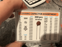
can i use these caps?i dont have good caps.
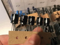
i have 16V elkos also. but what is better?
Attachments

Yes, you can.
I could write a long story about class 1 and class 2 ceramic capacitors now, but the signal voltage across the coupling capacitor will be so many orders of magnitude below the ceramic capacitor's voltage rating that it will work fine no matter what class it is.
For the electrolytic capacitor, I'd check which fits on the PCB best, the 16 V or the 63 V part. If it makes no difference, use the 63 V part, as those usually have a slightly lower effective series resistance.
Damn. Long story short tale. The microphone is broken. Somehow I must have shorted it out. I have ordered new ones. But I don't have one now.
I have another question. How do I get the noise to not go from one microcontroller to the other?
I have 2 microcontrollers running now with different power supplies. And they have no direct connection to each other except the 230V phase and neutral.
Or do I need to filter the noise with this for example?:
https://www.ldovr.com/ProductDetails.asp?ProductCode=LT3045-1A0G&CartID=1
Translated with www.DeepL.com/Translator (free version)
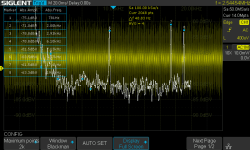
yesDo you see the noise with scope?
Attachments

Could these solve the alias problem?Your alias suppression will still be poor, but much better than at 44.1 kHz sample rate. For example:
-Suppose the microphone capsule itself has a second-order Butterworth roll-off with 20 kHz corner frequency.
-Suppose you add two first-order filters at 30 kHz, one made with C2 and one with a capacitor replacing R6.
The response in dB of a second-order Butterworth low-pass filter is -10 dB*log10(1 + (f/fc)4), while that of a first-order filter is -10 dB*log10(1 + (f/fc)2), where fc is the cut-off frequency (-3.01029... dB frequency). Cascading the second-order filter and two first-order filters, one gets:
20 kHz: total response at -6.2043 dB with respect to the low-frequency response
24.1 kHz (first alias of 20 kHz at 44.1 kHz sample rate): -9.2505 dB with respect to the low-frequency response, so 3.0462 dB lower than at 20 kHz
60 kHz (first alias of 20 kHz at 80 kHz sample rate): -33.1175 dB with respect to the low-frequency response, so 26.9132 dB lower than at 20 kHz
https://www.analog.com/media/cn/technical-documentation/data-sheets/2409.pdf
They could much improve it if you can let them run on an exact integer multiple of the ADC sample rate. Otherwise their clock feedthrough would cause aliases.
Thanks for the info.They could much improve it if you can let them run on an exact integer multiple of the ADC sample rate. Otherwise their clock feedthrough would cause aliases.
I also found a topic on this in the data sheet on page 12:
Anti-Aliasing and Post-DAC Filtering
When using the MAX7418–MAX7425 for anti-aliasing or post-DAC filtering, synchronize the DAC (or ADC) and the filter clocks. If the clocks are not synchronized, beat frequencies may alias into the desired passband.
So that I have understood correctly I would like to give an example.
ADC sampling rate is 44100 Hz.
Filter frequency 22050Hz. Does this make sense?
I'll give you a counterexample.
Suppose the band of interest is up to 20 kHz. You can then take the MAX7418 or MAX7422, both elliptical filters with a stopband starting at 1.6 times the end of the passband, and give it a clock frequency of 2 MHz. The clock frequency to corner frequency ratio is 100:1 according to the datasheet, so the corner frequency is then 20 kHz.
The stopband starts at 1.6 times 20 kHz = 32 kHz. If you want the filter to suppress all frequencies that could alias to frequencies below 20 kHz, the ADC sample rate must be at least 52 kHz. If you want it to suppress any frequency that could alias anywhere, the ADC sample rate has to be at least 64 kHz.
Meanwhile the ADC sample rate must be exactly the filter's clock frequency divided by an integer, so for the first case, you could use 2 MHz/38 and for the second 2 MHz/31.
The filter itself is also time discrete, switched capacitor filters always are, so it can generate aliases of its own. As its sample rate is as high as 2 MHz when it runs on a 2 MHz clock, only frequencies above 1.98 MHz could alias to below 20 kHz. The microphone capsule's roll-off will suppress such frequencies pretty well.
Last edited:
thank you for your detailed explanation. from tomorrow my vacation is over, so I will not be able to continue the project for the time being.
1. I try to filter the noise with the lt3045 away.
2. the microphone still needs to be re-soldered as soon as it arrives.
3. maybe i don't need to design my own microphone board. i'm still interested in it. do you think i could improve my application with it? if i could switch 2 gains via microcontroller, that would be very good. and the filter could go up with it.
4. as sampling rate i would use the 2MHz / 25 = 80kHz. then i could go to fs=40kHz with a software low pass. by disposing every 2nd sample after the sofware filter
Sorry I haven't had a few more minutes to read post #50 to here, but if you still haven't terminated the 4 separate !OE pins on the 'AHCT125's, please do so now. Leaving CMOS inputs to suffer stray coupling to fast signals is never wise, no matter what some Internet Guru advises. I'll continue reading.
I also strongly suspect SPI data rates are not needed for this application. Same with 16,7e6 colors. Same again with the 330 ohm pullups; 15mA is a lot of pullup for a multiplexed display data rate. If the WS2812B's can run slower, it might be worth checking out.
edit: Darn -- if I would've just read THE NEXT post . . Uuu-gh . .
Cheers
Last edited:
Can you imagine, if I replace all blue data line
(https://www.diyaudio.com/community/...ed-to-the-microcontroller.398277/post-7330125)
with a coax rg178 line, that the noise will improve? What do I do with the shield?
(https://www.diyaudio.com/community/...ed-to-the-microcontroller.398277/post-7330125)
with a coax rg178 line, that the noise will improve? What do I do with the shield?
with what?but if you still haven't terminated the 4 separate !OE pins on the 'AHCT125's, please do so now.
Try it and you will see. On the driving side, you can use a series resistor with a resistance equal to the characteristic impedance of the cable minus the output resistance of the logic gate that drives it. That should prevent the signal from bouncing up and down the cable repeatedly (limit transmission line reflections by series termination).
Regarding the shield: you have to connect the shield to ground on the driving side, on the receiving side you can try grounding it directly or grounding it through a capacitor to see what works best.
I think Rick PA Stadel retracted his remark after reading one more post. He just meant that the output enable not inputs have to be grounded, which they already are.
I tried to read it in in an antique version of Eagle that I have somewhere on my computer, but that only led to an error message. Fortunately they have it in a more generic format on https://learn.adafruit.com/adafruit-microphone-amplifier-breakout/downloads I think the creative commons license (see your github link) allows me to share it here, so here you go:
View attachment 1166552
Connecting a 100 uF electrolytic capacitor in parallel with C1 and a 100 nF capacitor in parallel with C2 should make this circuit far less sensitive to ripple on its supply. There is no need to replace the the resistor that supplies the microphone capsule with two resistors in series, as it's already two in series.
Hello Marcel,
I now have time to continue my project. Right now I can't use it at all and that's a pity. I would like to make it executable again.
I now have new microphones and would like to change the, as you described above.
Can you explain what exactly changes there and why you want me to do that?
Hi XerXes777,
I don't remember the details of this thread, but I think you had a crosstalk issue from a microcontroller to a microphone/microphone preamplifier board, and there was some reason to believe it might partly or completely couple via the supply.
The circuit shown in https://www.diyaudio.com/community/attachments/1166552/ uses a low-pass filter consisting of R2 and C1 to suppress interference on the supply, but it can be made more effective at low frequencies by using a much bigger capacitor. Unfortunately C2 and R4 then limit the efficacy, which can be solved by also increasing C2.
Regards,
Marcel
It seems not to affect the performance at all, the voltage noise density plot is clean up to 1MHz or more - I suspect its freq much higher than that and is billed as low noise charge pump - however it probably means decoupling advice is mandatory.According to chapter 7 of its datasheet, see https://www.ti.com/product/OPA322 , the OPA322 uses a charge pump for its input stage. If the charge pump switching frequency ends up at the ADC input, it might alias to an audio frequency.
I'd suggest that for audio use an audio ADC - ie I2S output, separate analog supply (always desirable for audio sampling). These chips are almost always sigma-delta and don't suffer from issues at mid-range like SAR ADCs do, and have wide dynamic range (24 bit is common). That does mean your microcontroller has to support I2S of course, which may be inconvient...
- Home
- Design & Build
- Construction Tips
- Strong noise floor when the mic is connected to the microcontroller