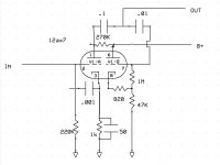
I would suggest it's probably been drawn out wrongly?.
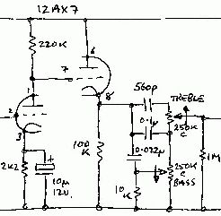
The left half is a common cathode stage, the right half a common anode stage giving a low (in valve terms) output impedance from it's cathode.
The left half is a common cathode stage, the right half a common anode stage giving a low (in valve terms) output impedance from it's cathode.
I drew this from the actual amp, it is correct. I am unable to find a schematic.
I presumed you're drawn it, and I 'presume' it's not quite correct - there should be something (an output) connected to the second cathode, pin 8. Assuming this is hard wired? (and not a PCB) sometimes it's easy not to be able to see a connection.
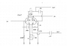
It is point to point not a PCB. I do now see another wire from the second cathode, It goes to a cap then on to a socket for an external speaker cabinet. I didn't notice it before, it is quite cramped in there. Now it makes sense, thank you for pointing that out.
Attachments
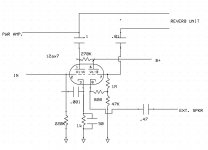
What's the thing driven from? I thought at first the .001µF on the input was a bootstrap, but there's a cathode bypass capacitor, so it's essentially rolling off high frequencies.
And while the cathode follower is giving a decently low output impedance, with that 47k it's not capable of driving current into it.
And while the cathode follower is giving a decently low output impedance, with that 47k it's not capable of driving current into it.
The organs tone generator was connected to the input, the first output goes to the power amp and internal speakers, the second output would have gone to an optional amplified speaker cabinet.
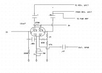
Those are quite standard circuits used since the 50's in guitar amplifiers.
Check the tone stack driver used in Fender Tweed Bassman or all Marshalls or VOX Top Boost.
Check the tone stack driver used in Fender Tweed Bassman or all Marshalls or VOX Top Boost.
I Now it makes sense, thank you for pointing that out.
I've drawn a LOT of circuits out over many years - if it doesn't make sense it's almost always because you made an error 😀
In this case it didn't help the actual way you had drawn it (I usually draw it out roughly, and then rearrange it to be in a normal configuration), but it was a standard looking circuit IF there was a connection to the second cathode, and no reason for the second triode if there wasn't any connection.
The thing with drawing circuits out is you really need to know what it's going to look like before you start 😀
- Status
- Not open for further replies.
- Home
- Live Sound
- Instruments and Amps
- strange preamp