
Repair problem AM-U61
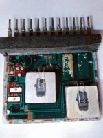
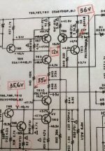
After replacing the STK1080 ii of the right channel, it is not possible to adjust the voltage of 47.7v on the TR6 and TR8 collectors (actually 36v). Transistors, diodes and zener diodes around STK1080 have been tested.I NEED HELP ! Asking for advice. Thank you.
After replacing the STK1080 ii of the right channel, it is not possible to adjust the voltage of 47.7v on the TR6 and TR8 collectors (actually 36v). Transistors, diodes and zener diodes around STK1080 have been tested.I NEED HELP ! Asking for advice. Thank you.

Thank you for reply !
All resistors , diodes , transistors around TR 6,8,10,11,12 checked ! May be TR 10 not full good ? I will buy it in 2 weeks. Voltages on both STK pins perfect.
All resistors , diodes , transistors around TR 6,8,10,11,12 checked ! May be TR 10 not full good ? I will buy it in 2 weeks. Voltages on both STK pins perfect.
What are your *rail* voltages
Those come straight from main power supply and are not "adjustable", you have what you have.
Are you using a lamp bulb current limiter?
Or a Variac?
Those come straight from main power supply and are not "adjustable", you have what you have.
Are you using a lamp bulb current limiter?
Or a Variac?
Hello. Great job! I encountered the same problem with the same amplifier. May I ask if other transistors are suitable for replacement? I have TIP122/127 and BD139/140Hello, All --
Did an all up Performance Test after playing it for a couple of hours.
The result was 75 V p-p into 8 Ohms, which equates to 87.5 Watts RMS, measured with 1 Khz Input; that is just short of Akai's 88 Watts. That was with only One channel Driven.
No sign of any sort of instability, so that's good.
if Any One wants the Artwork for my PC boards, just ask.
Thanks for all help received; I'm really thankful for that.
Attached is the Output, just short of clipping, as viewed on the 'Scope.
Hi Folks, just my 2 cents; I have a replacement STK1080ii on it's way from overseas but from what I've read here, it will probably not work. At the risk of sounding like an STK hater, I feel they are at a disadvantage from the start because they have an extra thermal barrier between the output transistors and the heat sink. This problem is compounded by the use of the heat pipe. Isn't the purpose of a heat pipe to conduct the heat away from the heat producing devices? This heat pipe does a U-turn and brings the heat right back behind the STK mounting plate.
I am very tempted to replace the output section with a couple of discrete power amps from a scrapped home theatre receiver. At first glance, there seems to be lot's of room once the STK's and heat pipe assembly are removed. I was considering amps from a 100 WPC (into 8 ohms) Denon home theatre receiver but the the AKAI B+ and B- voltage is 53 V. The Denon B+ is 43 V. Strange.
I am very tempted to replace the output section with a couple of discrete power amps from a scrapped home theatre receiver. At first glance, there seems to be lot's of room once the STK's and heat pipe assembly are removed. I was considering amps from a 100 WPC (into 8 ohms) Denon home theatre receiver but the the AKAI B+ and B- voltage is 53 V. The Denon B+ is 43 V. Strange.
https://www.eevblog.com/forum/repair/stk1050ii-1080ii-and-stk-3056-3076-new-replacements/
21'st century STK1080 looks cool ! Hmm , sanken outputs.
21'st century STK1080 looks cool ! Hmm , sanken outputs.
Attachments

have you made pcb's ?
I’m down for 2 pcbs can you make some more please?STK1080 Devices
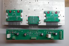
Well, I seem to have had significant success.
I mounted the Output Devices onto a piece of 5 mm Thick Aluminum which I have attached to the Amp's Heatsink with Thermal Paste and screws.
After powering it up on the Variac, I slowly Increased the supply voltage up to our normal 230 Vac while monitoring the Quiescent Current, which I have set to 15 Ma in both channels. I have also attached the Vbe Multipliers to the heatsink and these appear to be doing what they should. After watching it for a while to see where things were going, I connected up the Oscilloscope and lo and behold, it seems to be Rock Stable, which is good considering there is probably some extra wire length in there between the mother board and my additions. Then I connected a set of speakers while still monitoring the outputs, all good. Then, a Signal Source to the input; and it sounds great.
Tomorrow I will give it a Power Output Test into my Fan Cooled Resistor Stack and see what is what. In the Final Build, I used .33 of an Ohm Emitter Resistors as I believe this might help the Thermal Stability and Current Limiting to activate a little earlier. I have attached some shots of the exercise. Thanks to All who have given help!
I’d like two of your artworks plsHello, All --
Did an all up Performance Test after playing it for a couple of hours.
The result was 75 V p-p into 8 Ohms, which equates to 87.5 Watts RMS, measured with 1 Khz Input; that is just short of Akai's 88 Watts. That was with only One channel Driven.
No sign of any sort of instability, so that's good.
if Any One wants the Artwork for my PC boards, just ask.
Thanks for all help received; I'm really thankful for that.
Attached is the Output, just short of clipping, as viewed on the 'Scope.
- Home
- Amplifiers
- Solid State
- STK1080II Devices