If you mean the Acoustat-X listening to them is my only remaining memory from that era's audio shows. They left an impression. A pair were offered for sale here not long ago but didn't attract a sniff.
Charles Hansen said:The 844. [snipped rest to save bandwidth]
Charles, thanks for that peek behind the scenes.
Thought so. The '844 is one of the most underrated chips for audio. It's buffer for instance is excellent as an open loop input buffer, see attachment. (Input to pin 5, output from pin 6).
I guess the way you used it was in a pair, just like one would use a Maxim 435/436. The Maxims aren't as linear though.
Jan Didden
Attachments
Jan,
it is the AD844 frontend, that is excellent. It is probably one of the best line level audio opamp stages.
it is the AD844 frontend, that is excellent. It is probably one of the best line level audio opamp stages.
So the trick with AD844 is to load the TZ node to get the OL gain down (for AC at least, running a DC stabilizing loop around it)? And maybe use two of them (-IN's connected via a R) and shift currents between them, forming a fully differential gain block (probably to be used in a super-symmetric fashion as well)?
Klaus
Klaus
john curl said:I don't like high feedback regulators applied DIRECTLY to amplifier stages. I always use an open loop cap multiplier equivalent buffer between the IC power reg and the amp stage.
They're going all crazy about such things right now on pinkfishmedia...
For example : http://www.pinkfishmedia.net/forum/showthread.php?t=39990 or http://www.pinkfishmedia.net/forum/showthread.php?t=36174
Good question. Low value resistors return two entities. First, a current dependent voltage..second, a voltage dependent on the rate of change of current through the resistor, due to dI/dt. I had this exact problem with a 250 microohm resistor.GRollins said:Unfortunately, there are only three options. You can load the line capacitively, inductively, or resistively. At some point, you're going to find that what you're using as a sensor is going to have an effect on the thing you're measuring. How much? That will depend on the sensitivity of the circuit behind the sensor. Use a sensitive enough circuit and you can use a .0001 Ohm resistor, which is going to have a pretty minimal effect on the measurements.
Or is it?
So I made better ones. 250 picohenry**, 4 ohm, 40 watts. Good enough for gov't woik..
Cheers, John
ps..** Actually 60 picohenry, I just couldn't get the meter to accurately read below 250pH. Geometric limits of the resistor physical size.
janneman said:
Charles, thanks for that peek behind the scenes.
Thought so. The '844 is one of the most underrated chips for audio. It's buffer for instance is excellent as an open loop input buffer, see attachment. (Input to pin 5, output from pin 6).
I guess the way you used it was in a pair, just like one would use a Maxim 435/436. The Maxims aren't as linear though.
Jan Didden
PMA said:Jan,
it is the AD844 frontend, that is excellent. It is probably one of the best line level audio opamp stages.
To both I totally disagree!
AD844BS
:bs:
GRollins said:There have been numerous posts in addition to Bob Cordell's letter in Stereophile claiming that the passive components in chips are of equivalent quality to stand alone discrete components. Are any of you guys going to post accurate detailed specifications for actual chip passive components or are we just supposed to take your word for it that they're wonderful?
Stand and deliver, guys. You're always chanting, "Prove it! Prove it!" to those who listen...now the shoe's on the other foot. I think most people (myself included) would say that some actual numbers on those parts would be useful, so either post hard numbers or desist with extolling the virtues of chip passives. I, for one, am unpersuaded.
Grey
You are such a debator, Grey. I would actually like you guys to post hard numbers on very expensive discrete resistors vs ordinary high-quality discrete resistors (metal film, for example) that relevantly show why the former sound better.
Mind you, I am not saying that the former don't sound better (don't exercise your habit of putting words in my mouth). I'm saying that it is often tough to measure those things that are at work in a relevant way to make the sound better or worse or just different.
Cheers,
Bob
Charles Hansen said:
I have three pieces of data that support my assertion. The first was back in the dawn of high-end history. The Audio Research SP-3 had a capacitance multiplier voltage regulator. I think the reference was a string of zeners (bypassed with an electrolytic cap), and the pass device was a bipolar power transistor in a TO-3 can. (By the way, this was probably the main reason that it sounded better than the otherwise very similar Dynaco PAS-3.)
Then there was a small company in Paoli, PA that made a HV regulator using a floating 3-pin regulator as an add-on PCB for the SP-3. My friend put it into his preamp (I certainly couldn't afford one then!). The sound become much more detailed, the bass tightened up, and the soundstaging become much more focused. But after a few months we noticed that we simply weren't listening to as much music and when we did we weren't enjoying it as much.
The second time this happened, I took a Dyna Stereo 70 and rebuilt it with the Curcio input board from the mid-'80s. This had a cascoded driver stage with a diff-amp as the phase splitter. It also had an on-board regulator for the front end circuit. Of course, this was a high-feedback design based on some op-amp. It was funny to listen to -- we called it "goo and shine". You could hear the "gooey" signature of the electrolytic cap used across the voltage reference, along with the zingy "shine" provided by the high feedback regulator circuit. I redesigned the regulator to a zero-feedback design using only PP film caps, and then that amp really began to sing. Running it as a triode output stage made it one of the best amps I'd ever heard up to that time, although it would only put out 18 watts per channel.
Finally, New York Audio Labs used to make a phono stage called the "Super-It". It had a JFET input for low noise and a tube as a cascode for the JFET. I think it had another tube or two for more gain. Once again it had a high-feedback op-amp based regulator. Replacing with a zero-feedback regulator (again using JFETs so that a PP cap would be sufficient to bypass the voltage reference), and that thing sounded absolutely superb. (I also replaced all of the coupling caps with better parts.)
Anyway SY, you may want to try some experiments. E-mail me the schematic of your existing regulator, and I'll e-mail back something that I think will sound better. You can try it and report back to me.
Cheers,
Charlie Hansen
Hi Charles,
This is very interesting, and thanks for posting your experiences on this. What is your theory on why the use of a high-feedback power supply regulator will make the sound worse?
For example, if the two regulators exhibit the same amount of stiffness, and a look at the regulated line shows no evidence of noise, or nonlinear signal, or bounce on it, or signs of HF oscillation, what do you think it could be?
Obviously, it is possible for someone to screw up the design of a high-feedback regulator, but I am assuming that we are talking about competently well-engineered examples of both here. By the same token, I am assuming that a potentially less-stiff non-NFB regulator is not making the sound different in a way that happens to be pleasing.
Thanks,
Bob
Charles Hansen said:
(I had a brief e-mail correspondence with Mr. Gilbert. He is a brilliant engineer, but he thought I was fool to avoid the use of feedback. His main argument was that no matter how linear of a circuit I made, the distortion could always be lowered by using feedback. I had the same question for him as I do everyone else here -- if I can achieve 0.001% distortion without feedback, why bother adding feedback? Do you really think that we can hear 0.001% distortion, but not 0.0001% distortion?)
Hi Charles,
I think both you and Barrie have valid points. They are not mutually exclusive. And indeed, it is a fair question, why use NFB if you can achieve 0.001% distortion without it?
I think I largely agree with you on this, with perhaps a couple of caveats. First, I pretty much think getting down to 0.001% THD-20 measuring all harmonics out to the tenth is pretty much good enough as long as there is not some really gross anomaly. Similarly, I'd probably say that getting all in-band CCIF IM products below -110 dB or so would likely suffice.
And, of course, the amplifier must be fundamentally well-enough behaved that the 0.001% performance is reasonably characteristic of how it performs under dynamic and difficult-load conditions. This goes for both the NFB and non-NFB amplifiers that both meet the 0.001%.
Getting to 0.001% without NFB is, I think, pretty difficult in a power amplifier. You've done a great job in your MX-R without NFB, but here we are talking another order of magnitude plus. I'd imagine that it would end up being a much more expensive and bulky amplifier, and far more costly. Given that any consumer product, high-end or not, is not cost-is-no-object, it may come down to where we best spend our budget. If we can get the objective and subjective performance to be just as superlative by using feedback at less cost, maybe we spend the extra budget dollars on more power, or maybe just make our product more affordable.
I note that, given enough transistors and bias and beef in the output stage, we can even get the output impedance of the no-NFB amplifier down so low as it can't possibly matter.
Cheers,
Bob
john curl said:I don't like high feedback regulators applied DIRECTLY to amplifier stages. I always use an open loop cap multiplier equivalent buffer between the IC power reg and the amp stage. I didn't know this 35 years ago, when I designed the JC-2, I just 'lucked' into it, when buffering studio board stages from each other. That is how the Wilson Audio master tape recorder electronics were designed, and the Crystal Clear studio board, among other projects. Please consider that I use vinyl records made from these companies among my reference sources, just to have a more complete chain of high quality electronics from source to speaker.
These 'suggestions' much like: "Eat an apple a day, and keep the doctor away" are learned by experience and often by accident, and are often scoffed at by the 'typical scientists' of the time period. In this case, some engineers on this thread.
Hi John,
For all we know, you might be right. But the interesting question would then be why? I think it is a fascinating question, but I don't think I have heard an answer to the "why" that makes sense.
Cheers,
Bob
Bob Cordell said:Obviously, it is possible for someone to screw up the design of a high-feedback regulator, but I am assuming that we are talking about competently well-engineered examples of both here.
This is an interesting point. My view of what might be going on is mostly speculation, but here goes anyway...
Some regulators such as Walt's "super reg" topology are more difficult to get right than a simple EF/capacitance multiplier. Depending on the op-amp used, their unity loop gain freq might be 3-10 MHz. So they can easily oscillate with a load capacitor having a very low ESR. Suppose somebody builds one and determines that it oscillates with a 0.1uF cap directly at the output. They remove the cap and all is well. Is this the end of the story? No, because they or someone else may hook up this reg with very short leads or traces to a bunch of op-amps or discrete circuits, each having, say, a 0.1uF cap for bypassing. Is the lead length or trace length enough to keep the reg not only stable, but also maintain good transient response of the reg (as John mentioned above)? Maybe yes, maybe no. One way out of this it to put something like 0.22 Ohm resistors in series with the bypass caps, but how many people do this?
One way out of this it to put something like 0.22 Ohm resistors in series with the bypass caps, but how many people do this?
Well, it's not 0R22 (the voltage and current levels are different here), but...
http://www.diyaudio.com/forums/attachment.php?s=&postid=940352&stamp=1150303126
OT: Have you read Taber's newest book?
john curl said:Transient response?
Yes, in a poorly-designed NFB regulator.
But you would expect to see the results of bad transient response of the regulator on the regulated lines. For example, bad regulator transient response might cause certain HF voltage changes on the input side to fly through to the output side. One would expect to see that on the regulated rails. Moreover, one can test that in the lab by deliberately putting disturbances on the input side and seeing what happens to the output side.
Similarly, bad transient response in reaction to sudden changes in the load current would be expected to be seen as a voltage change on the load side rails. And of course that could be demonstrated in the lab by deliberately applying current deviations to the load line.
If you are saying that there are NFB regulators out there that are inadequately performing in this regard, then I probably agree with you.
If, on the other hand, you are saying that NFB regulators fundamentally cannot perform well in this regard because they use NFB, then I would disagree with you.
Cheers,
Bob
SY said:Well, it's not 0R22 (the voltage and current levels are different here), but...
http://www.diyaudio.com/forums/attachment.php?s=&postid=940352&stamp=1150303126
There you go! 🙂
OT: Have you read Taber's newest book?
OT: No, the first time I found out about the "Back to France!" quote was today, and I laughed so hard I actually forgot about the stock market!
john curl said:I agree, PMA, but you are still 30 years away from what I am doing today. Keep working on it.
Pavel, John
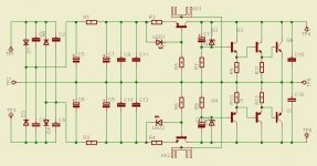
I agree that a high feedback regulator can destroy the sound.
I use this with very good results for frontend in my power amp.
Mihai
Attachments
- Status
- Not open for further replies.
- Home
- Amplifiers
- Solid State
- Stereophile, January 2008, pages 13 and 15