just put in the bid and it seem like its going to be more than $20.00, i've been outbid at $22.50 so far i dont know if i want to get in to a biding war.
I unfortunately put in a max bid of $25 so until you bid over $25 you will not win it. I won't bid any higher, I am out if you want it. It is a UTC so it is worth every penny of $25 and will probably not sell for any higher. I have been buying alot of these up lately and it seems the market is down on them. If you don't want to pay over $25 and I win it for whatever it is up to now, you can have it for what I pay and I will just have him send it your address. You can just pay me after the bidding ends. So, really, I wouldn't bid on it anymore so we can keep the cost down. Just let me know and it is your (If I win it of course). I wouldn't pay anymore than $25 or so for it b/c you could buy a Hammond with S/H for about the same when it is all said and done. I like the vintage potted chokes, they are very nice and built to last forever. My Westinhouse weighs about 11#!
Jeff
HI GUYS!
So i didnt win the auction for the choke so i got one from angela 10h@200ma it came in yesterday did some mock up and it fit nicely.
This project was originally for RH807 but now i wanted to built it with KT88 after i follow this thread so i have a question. can i use the RH807 schematic to be use with KT88. or i need to change it intirely to the one on this thread.
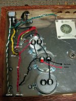
oh and heres some pic of the project so far.
So i didnt win the auction for the choke so i got one from angela 10h@200ma it came in yesterday did some mock up and it fit nicely.
This project was originally for RH807 but now i wanted to built it with KT88 after i follow this thread so i have a question. can i use the RH807 schematic to be use with KT88. or i need to change it intirely to the one on this thread.
oh and heres some pic of the project so far.
Attachments
PSU: Why is my 5U4G burning out?
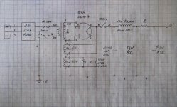
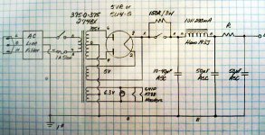
I powered up only the PSU just to see if it works. I didn't hook up C3 yet because I want to determine if I need a R between C2 and C3, so I hooked up the test leads from C2. The layout and schematic is shown below.
I first turned the power on, then after 15seconds I turned the standby on. The tube began to warm up. After 30 seconds the 1A fast blow fuse burned out. I didn't have a 1A slow blow fuse, so I could only use a 10A ceramic fuse.
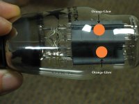
After replacing the fuse with a 10A fuse, I turned the power on, then the standby after 15seconds. After about 20-30seconds I saw a 1cm orange glow the middle of each grey plate of the 5U4G tube then a faint "puff" and the PSU went out by before I could measure the voltage.
I finally bought 1A slow blow fuses, and replaced them. But the new Sovtek tube doesn't work anymore. I'd like to avoid spending $50 every time I turn power on... 😕
Questions:
1. Why is the NEW Sovtek 5U4G burning out?
2. Does it make a difference if I have the "N" going to the fuse and the "L" going to the switch from the IEC Line Filter? (The included "N" wire on the Line filter didn't reach the the Pwr Switch so I used the "L" wire).
3. Is the 40uF C1 to high for this circuit?
4. Should there have been be a load at B+?
I could use some help here. Thanks Guys!
I powered up only the PSU just to see if it works. I didn't hook up C3 yet because I want to determine if I need a R between C2 and C3, so I hooked up the test leads from C2. The layout and schematic is shown below.
I first turned the power on, then after 15seconds I turned the standby on. The tube began to warm up. After 30 seconds the 1A fast blow fuse burned out. I didn't have a 1A slow blow fuse, so I could only use a 10A ceramic fuse.
After replacing the fuse with a 10A fuse, I turned the power on, then the standby after 15seconds. After about 20-30seconds I saw a 1cm orange glow the middle of each grey plate of the 5U4G tube then a faint "puff" and the PSU went out by before I could measure the voltage.
I finally bought 1A slow blow fuses, and replaced them. But the new Sovtek tube doesn't work anymore. I'd like to avoid spending $50 every time I turn power on... 😕
Questions:
1. Why is the NEW Sovtek 5U4G burning out?
2. Does it make a difference if I have the "N" going to the fuse and the "L" going to the switch from the IEC Line Filter? (The included "N" wire on the Line filter didn't reach the the Pwr Switch so I used the "L" wire).
3. Is the 40uF C1 to high for this circuit?
4. Should there have been be a load at B+?
I could use some help here. Thanks Guys!
Attachments
Last edited:
I powered up only the PSU just to see if it works. I didn't hook up C3 yet because I want to determine if I need a R between C2 and C3, so I hooked up the test leads from C2. The layout and schematic is shown below.
I first turned the power on, then after 15seconds I turned the standby on. The tube began to warm up. After 30 seconds the 1A fast blow fuse burned out. I didn't have a 1A slow blow fuse, so I could only use a 10A ceramic fuse.
After replacing the fuse with a 10A fuse, I turned the power on, then the standby after 15seconds. After about 20-30seconds I saw a 1cm orange glow the middle of each grey plate of the 5U4G tube then a faint "puff" and the PSU went out by before I could measure the voltage.
I finally bought 1A slow blow fuses, and replaced them. But the new Sovtek tube doesn't work anymore. I'd like to avoid spending $50 every time I turn power on... 😕
Questions:
1. Why is the NEW Sovtek 5U4G burning out?
2. Does it make a difference if I have the "N" going to the fuse and the "L" going to the switch from the IEC Line Filter? (The included "N" wire on the Line filter didn't reach the the Pwr Switch so I used the "L" wire).
3. Is the 40uF C1 to high for this circuit?
4. Should there have been be a load at B+?
I could use some help here. Thanks Guys![/QUOTE
i am not such a expert but i don,t think that the l or the n make so much different ,cause you don,t know where the l is on the socket you plug it in ,
3 by duncan amp a 40u is the max value for your tube , it seems your stanby switch is in the wrong place ,if it would be open it could be the cause ,,atualy if you use a rectifer tube i would leave the switch out of the schematics all together ,if you want to put is you can put it on the end of the filter ,i think now your fillament is burned out ,you can try what the amp does bij using a diode bridge ,before you try a other tube ,you can buy the 5u4 straight from rusia on ebay for about 10 dollar the tube [svetlana]
i would measure your first c on shorts with a capitator measure
hope this helps a litlle ,replacing a fuse with a slow blow is a good idea , but you can not use of a higher value
,i would not conect the ground from the filter to the ground of the amp
greeting from amsterdam
Last edited:
For the 5U4 the maximal value of the first capacitor shouldnt exeed 33uF.
I cant tell you if that is the reason though.
I cant tell you if that is the reason though.
Ops!
You seem to have grounded the 5V heater (if the very nicely drawn diagram is correct)
That will short the rectifier tube to gnd.
Svein.
You seem to have grounded the 5V heater (if the very nicely drawn diagram is correct)
That will short the rectifier tube to gnd.
Svein.
It looks like there is a CT on your 5v winding for the rectifier and it looks on the schematic that you have it grounded. If this is the case you should be taking B+ from that CT and not pin 8. Is this the case?
Questions:
1. Why is the NEW Sovtek 5U4G burning out?
2. Does it make a difference if I have the "N" going to the fuse and the "L" going to the switch from the IEC Line Filter? (The included "N" wire on the Line filter didn't reach the the Pwr Switch so I used the "L" wire).
3. Is the 40uF C1 to high for this circuit?
4. Should there have been be a load at B+?
I could use some help here. Thanks Guys!
1. It is not the Sovtek 5u4g that caused the problem.
3. 40uf is too much for 5u4g, if you use more than 10uf, the B+ with full load will be higher than 400VDC.
Don't ground the 5V CT going to the heater of the rectifier tube, you are effectively shorting the B+.
Install the standby switch on the CT of the 375-0-375 secondary winding. The reason I installed it on my build is because I was using 450VDC capacitors and the 5u4gb does not ramp up the voltage slowly, but rather, it is gives full power before the tubes conduct, hence, I was getting B+ for about a minute or so at 500+VDC. One early morning (3AM), while working on the amp, one of the capacitors exploded!
The original schematic from the OP depicts a 40uf cap, I've read through this whole thread but it's been a couple of weeks. Can I assume the circuit has been revised with lower capacitance in the filter?
EDIT nm this is addressed around post 77
EDIT nm this is addressed around post 77
Last edited:
for the first capicitator after the 5u4gb i use 2X 47uf 400volts elco,s in serie
wich gives a plus minus 47 uf 800volt buffer elco , works very good in my amp then comes a 12h 400ma choke then a 150 uf 600volt elco
as retifer tube a jan philips 5u4gb , i use a 30 year big [4,5 kilo] old trafo from a kt66 push pull with 375 0 375 enough ma ,
in the tdsl from duncan amps i found a max 0f 40 uf for the first buffer cap
,i gues that aspecaly with asr a lower value would be much better
then with traditional caps grtz ko
..... i use 2X 47uf 400volts elco,s in serie
wich gives a plus minus 47 uf 800volt buffer elco ......
Actually, two 47uF capacitors in series will equal one capacitor with 1/2 the original capacitance with twice the voltage rating, or 23.5uF/800v in your case.
Jeff
Actually, two 47uF capacitors in series will equal one capacitor with 1/2 the original capacitance with twice the voltage rating, or 23.5uF/800v in your case.
Jeff
hi jeff
your absolutly right , i ment 2 capicitators 100uf 400volt [nos philips]
with the capacitator terster it came to 47,3 uf ,its a bit to high for the 5u4gb
i was reading in the tdsl a value of 40 max , but is a philips jan [joined army navy ] tube and they
are pretty strong ,and in the psud2 it worked out great
grtz ko
Standby Switch
Here is a great article concerning the "standby switch". Breaking the center-tap still leaves the rectifier at high potential. I chose to break both leads of the secondary. While this does require a DPDT switch (actually it requires a DPST switch, but usually you will find that the DPDT is more readily available), it totally removes HT from the rectifier. The ultimate design would be to size the working-voltage of the capacitors such that the initial high-voltage would pose no problem, hence eliminating the need for the standby switch.
Also I agree, if using a 5U4GB, take the HT from the 5V center-tap.
http://www.freewebs.com/valvewizard1/standby.html
PS: I used an Ampohm 30uF/630V metallized polypropylene for the first capacitor with excellent results.
Last edited:
Modified PSU Schematic
Thank you everyone for all your useful input! As a newbie, I would've never guessed that I shouldn't ground a 5VAC CT going to the rectifier - Now I know to not ground all CT! I've been bogged down for 3 months having to chose from 5 different schematics for this project. I really don't want to scrap the wooden frame and chassis because of the C1 and standby switch.
I am going to chance using a SPST standby switch and a 40uF C1 because they're already mounted. I initially figured the higher capacitance would help with ripple (up to 40uF of course for a 5U4G). If I blow another rectifier, then I'll have to start the entire construction from scratch by using a 10uF for C1 as Alexg stated.
BTW, all my ASC caps are rated 440VAC (600VDC+)
QUESTIONS: (even the obvious)
1. Should I use the two 5VAC terminals for the rectifier heaters, and ignore the 5V CT?
2. Can I use a SPST standby switch in my current position and parallel it with a 150k/5W resistor as in the valvewizard article, by placing it between the tube rectifier and 40uF C1?
3. Should I NOT ground the 6.3VAC CT too?
Modified schematic shown below.
Seel34, Herr Grau, Svein, Mctavish, Alexg, jmillerdoc, scitizen17... Couldn't do it without you guys!
Attachments
hello . i would disconect the ground of the line filter ,actualy
you can leave out the line filter altogether , in the amps i build
it never gave any improvement , just problems
but i live in amsterdam ,and have a 230volt net current so it might be different
in the states
i would conect the 0 of the 6,3 to the zero of the amp
the ground of the filter or net should not be conected to the 0 circuit
of the amp
grtz ko
You need to install a bleeder resistor on the PSU.
I usually use 300K 2 watt.
You need to ground all the CT's except the rectifier heater.
I usually use 300K 2 watt.
You need to ground all the CT's except the rectifier heater.
Just simply disconnect the CT of the 5V you already have hooked up, that should solve the problem. The line filter will give anywhere from about 30 to 70dB of filtering of CM line noise and is a good idea if you are not using a shielded transformer, if your not sure if your transformer is shielded assume it isn't (most are not). Rather than poopooing the 40uF why not just put a smaller cap in front of it and connect the smaller and the 40uF with a fairly low value resistor, one that won't cause much of a final voltage drop. This is what I did but I had a little higher rated trafo so I needed the voltage drop and I chose this stage to provide it. It will not change much at all if your final voltage is down by 3-5%. This way you can keep the 40uF mounted and provide increased ripple filtering. Basically just by installing an extra CR filter infront of the existing 40uF cap. Maybe use a 10uF (I did) and a 50R, sim it on PSUD2 and see where the highest value of resistor can be added and still keep the voltage on the B+ within a close tolerance. It is a thought.
Jeff
Jeff
Another thing I would add is another stage to the line filter. Place an X2 type 0.1-0.33uF cap in parallel with a 220k-330k 2 watt resistor and place this in between the earth tap on the line filter and your star ground.
Jeff
Jeff
Is there a reason why people feel there is even a need for a standby switch on this design?
Just asking.
Glenn
Just asking.
Glenn
- Status
- Not open for further replies.
- Home
- Amplifiers
- Tubes / Valves
- stereo SE kt88 build ... abdellah diyaudioprojects design