Will polishing to a mirror like finish help??
Assuming you don't need electrical isolation netween the plate and the heatsink, normal goop may not be the best choice. I have no clue what is but I have a hunch there's something better out there.
Assuming you don't need electrical isolation netween the plate and the heatsink, normal goop may not be the best choice. I have no clue what is but I have a hunch there's something better out there.
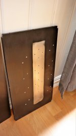
Yes polishing to a mirror finish will help but it also needs to be flat. This is bloody hard work to achieve if using equipment found at home.
I remember polishing a piece of welded steel cross-section approx 200mm x 200mm to characterise the macro and microstucture under a microscope. It took over a week of polishing 4 hours a day, and I still wasn't completely satsisfied with the result.
I remember polishing a piece of welded steel cross-section approx 200mm x 200mm to characterise the macro and microstucture under a microscope. It took over a week of polishing 4 hours a day, and I still wasn't completely satsisfied with the result.
Yes polishing to a mirror finish will help but it also needs to be flat. This is bloody hard work to achieve if using equipment found at home.
I remember polishing a piece of welded steel cross-section approx 200mm x 200mm to characterise the macro and microstucture under a microscope. It took over a week of polishing 4 hours a day, and I still wasn't completely satsisfied with the result.
But only the area under the mosfets need to be polished, and they don't need to be coplanar.. seems like a worthwhile effort, seeing this project is a (glorious, in a mad positive way) effort in extremes. Truly crazy would be polishing the mosfets..
I seem to recall that some amateur astronomers (another crazy bunch) make their own mirrors, and those are curved and need to be really precise.
I seem to recall that some amateur astronomers (another crazy bunch) make their own mirrors, and those are curved and need to be really precise.
Yup...and you can do it all by hand and test using the foucault test:
https://en.wikipedia.org/wiki/Foucault_knife-edge_test
Really quite remarkable...
AndrewT - Now that you know these images are huge, the easiest way to not have any issues loading this page is to look at other threads entirely, instead of this one.
😀 😀 😀
🙂 🙂 🙂
Also, please check the actual location of the images before spouting off about how they are not attached here.
😀 😀 😀
🙂 🙂 🙂
Also, please check the actual location of the images before spouting off about how they are not attached here.
it took over 1.5minutes to download this page because of the enormous files automatically downloaded from remote servers and then my protections prevented me seeing some of them because it has flagged those sites as "risky".
Why do you lot keep doing this remote server thing, when there is a far safer method built into the Forum "attachment" procedure?
But only the area under the mosfets need to be polished, and they don't need to be coplanar.. seems like a worthwhile effort, seeing this project is a (glorious, in a mad positive way) effort in extremes. Truly crazy would be polishing the mosfets..
Yes very true, and if you're prepared to go to the effort then it is definitely worthwhile, but to get all the scratches out it can be a bastard.
Last edited:
Sure WalterW.
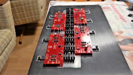
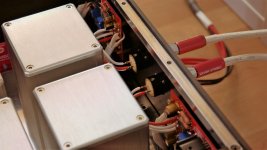
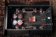
Sadly one ot the jfets where dead to, so I could not balance the bias/offset. I did not have any spare with hig enough idss, so I run two in parallel connection just to get the amp up and running. I have orderd more jfets so I can replace it.

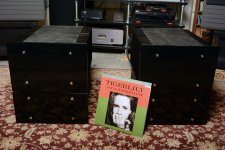
Yes, now its working!

Everything connected.

Now, testing!


Sadly one ot the jfets where dead to, so I could not balance the bias/offset. I did not have any spare with hig enough idss, so I run two in parallel connection just to get the amp up and running. I have orderd more jfets so I can replace it.
Yes, now its working!
Everything connected.
Now, testing!
Attachments
Wow, very very nice build!
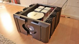
Thank you Walter. I am quite pleased myself, but if I would do it again there would be some small changes here and there. 🙂 Im maybe thinking about a bigger and more powerful F5 Turbo, but not decided whats next yet.
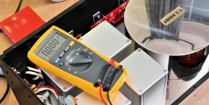
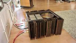
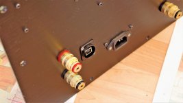
This one is still not finished. I have some plan for the round window in front, and it has to do with the USB connector in the back.
There is also another problem. I did a misstake when measuring, and I accidentally shorted something with my Fluke probes. Dont drink and measure!
 🙄 Well, the result is one fried channel. Even one of the rectifiers is smoked. I dont think I will repair it since the damage is extensive. Thinking it is better to build a completely new channel.
Attachments
Very nice build! Thats a lot of detail and hard work on the interior !
You want more power?! how many watts are you pushing now with this build?
You want more power?! how many watts are you pushing now with this build?
Very nice build! Thats a lot of detail and hard work on the interior !
You want more power?! how many watts are you pushing now with this build?
Thanks dazed2, it was a lot of work indeed. The SS surface was a pain in the xxx.
Last time this build was up an running it was running 110W class A. The heatsinks got 60 degree celsius, so its little to much. I think it will run stable and safe at 2x100W class A. The weight of the amp ended at 67kg.
Very nice build! Thats a lot of detail and hard work on the interior !
You want more power?! how many watts are you pushing now with this build?
For the next amp Im thinking around 2x300W class A. Depend of how big chassis I can get hold of. Maybe make chassis myself? Dont know yet. 🙂
Yes makes sense, I think a single chassis F5T3 generally tops out at about 100W classA due to heat issues.
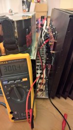
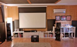
When I built mine they were mono blocks with separate PSU, and I'm able to crank it to about 160W class A with only a 19C above ambient temp rise. I guess I can go more, but never really bothered 🙂
Funny thing though I never found 160W lacking in any way, even with really hard to drive speakers in super large rooms.
Attachments
Last edited:
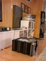
they're resembling DMT series , but with one bar too much
oops , DMT 15 is having 5 bars , sorta , with grills attached
which hard to drive ones ?
I woudn't call them hard to drive
oops , DMT 15 is having 5 bars , sorta , with grills attached
which hard to drive ones ?
I woudn't call them hard to drive
Last edited:
they're resembling DMT series , but with one bar too much
oops , DMT 15 is having 5 bars
which hard to drive ones ?
Wow you're good! Yes the ones behind the amp in that pic are DMT 215's but those aren't hard to drive. I had those amps hooked up to Watson Lab 10's, they seem to eat amps when driven loud. I think impedance swings down to 2Ohm does it 🙂
Last edited:
- Status
- Not open for further replies.
- Home
- Amplifiers
- Pass Labs
- Stereo F5 Turbo V3