Pictures far too big!
They are off-screen
Pleases re-size.
Im sorry if the big pictures are a problem. In my Microsoft Surface the forum automatically resize every photo. Are you on mobile?

You are maybe right about that, but with the insulators I think it will be ok.
Im using Laird Tgard 210.
I'm sure I'm right 😉 I have tested this, see: http://www.diyaudio.com/forums/pass...-anniversary-sony-vfet-clone.html#post4822395
Your outputs will be much hotter (too hot?) when mounted on the brushed aluminium. Even the other side where your heatsinks will be mounted, must be polished. Same for the heatsinks themselves, if you have the same as I have, I had to polish them for good heat transfer. They came in very heavily brushed.
The surface of the aluminium where the outputs are is quite smooth, but not smooth as when polished. I thought it would be no problem when using these insulators. I value your input, so thanks. I will look closer into this.
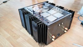
Superb build by the way, your amp looks awesome!
Thanks, I have built a F5 Turbo v3 also in the past and the biggest problems I had were temperature related. I think if you are building this amp, you want to crank up the bias as high as possible, so around 30Watt/ MOSFET, to have as much class A possible...
That's giving you 240Watt heat per channel, and that is an incredible lot of heat!
It would be a pity when you have wired everything up so nicely, you would have to unmount everything because MOSFETs are getting to hot on their plastic surface.
The insulators won't make the difference I guess, on a brushed surface.
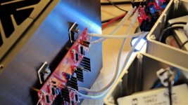
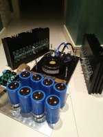
Love your build, love that big 2KVA transformer, your choice of components and your wiring!
I will be following this thread 😀
That's giving you 240Watt heat per channel, and that is an incredible lot of heat!
It would be a pity when you have wired everything up so nicely, you would have to unmount everything because MOSFETs are getting to hot on their plastic surface.
The insulators won't make the difference I guess, on a brushed surface.
Love your build, love that big 2KVA transformer, your choice of components and your wiring!
I will be following this thread 😀
Thanks, I have built a F5 Turbo v3 also in the past and the biggest problems I had were temperature related. I think if you are building this amp, you want to crank up the bias as high as possible, so around 30Watt/ MOSFET, to have as much class A possible...
That's giving you 240Watt heat per channel, and that is an incredible lot of heat!
It would be a pity when you have wired everything up so nicely, you would have to unmount everything because MOSFETs are getting to hot on their plastic surface.
The insulators won't make the difference I guess, on a brushed surface.
Love your build, love that big 2KVA transformer, your choice of components and your wiring!
I will be following this thread 😀
You see, I did run to high bias and the outputs are smoked.😀 New ones are on the way. Already unmounted everything. I will sand the surface before monting the pcb's again.
When done it will be something like this.
Attachments
Lot of painstaking work!
Especially all that polishing on the aluminum.
For the mosfets, you may benefit from a "spreader" between the mosfets and the heatsinks. This way you can optimize the mounting of the mosfets to a part that is not part of the back of a heatsink, and work with that separately. Then mount it to the heatsinks, relying upon the large surface area for heat transfer. Some people have even gone to copper for the spreader, but I am wary of electrolytic corrosion between copper and aluminum.
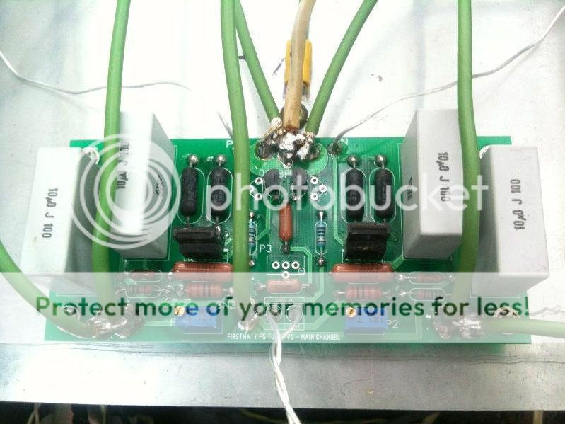
I don't have the schematic of this F5 version, what are the chokes for??
_-_-
Especially all that polishing on the aluminum.
For the mosfets, you may benefit from a "spreader" between the mosfets and the heatsinks. This way you can optimize the mounting of the mosfets to a part that is not part of the back of a heatsink, and work with that separately. Then mount it to the heatsinks, relying upon the large surface area for heat transfer. Some people have even gone to copper for the spreader, but I am wary of electrolytic corrosion between copper and aluminum.
I don't have the schematic of this F5 version, what are the chokes for??
_-_-
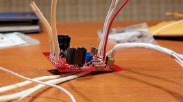
Very nice! Looks like you have some non-F5 boards in there. Are they inrush and speaker protection?
Lot of painstaking work!
Especially all that polishing on the aluminum.
For the mosfets, you may benefit from a "spreader" between the mosfets and the heatsinks. This way you can optimize the mounting of the mosfets to a part that is not part of the back of a heatsink, and work with that separately. Then mount it to the heatsinks, relying upon the large surface area for heat transfer. Some people have even gone to copper for the spreader, but I am wary of electrolytic corrosion between copper and aluminum.
I don't have the schematic of this F5 version, what are the chokes for??
_-_-
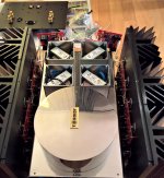
The bottom are aluminium, but the rest is stainless steel. Harder to polish, but it work good as a shield.
Thanks for the tip. Im not sure it is enough room inside the amp for spreader.
I run CLC psu, so the chokes are in the psu.
Very nice! Looks like you have some non-F5 boards in there. Are they inrush and speaker protection?
Yes, you are right. The one in the middle are inrush and the two others are speaker protection.
F5 V3
Hi TorH,
I really like your project, congratulations!
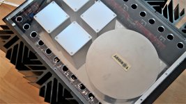
I want to ask you, between the large plate (10mm thick) and heatsink... you put thermal paste?
I have the same casse. I used thermal paste between:
- Aluminum plate and insulator Al2O3 (IRFP240 / 9240);
- Between thick plate and heatsink.
Maybe I'm wrong, but at a bias of 3.6 A heatskins temperature is around 48 ... 50 C.
Hi TorH,
I really like your project, congratulations!
I want to ask you, between the large plate (10mm thick) and heatsink... you put thermal paste?
I have the same casse. I used thermal paste between:
- Aluminum plate and insulator Al2O3 (IRFP240 / 9240);
- Between thick plate and heatsink.
Maybe I'm wrong, but at a bias of 3.6 A heatskins temperature is around 48 ... 50 C.
Attachments

Hi vitalica.
I belive we have been in touch before. Your amp looks really nice.
Between the outputs and the 10mm aluminium plate I use Laird Tgard 210 insulators instead of paste. Between the heatsinks and the aluminium plate I not have anything, but I was thinking about using paste. It is maybe better to polish the surfaces and not use any paste at all. Im not sure.
Hi TorH 🙂
From my experience I have had good results everywhere with just thermal paste.
I thought, even if it is polished, everything must be put thermal paste.
I look forward to news from you, a great project!
From my experience I have had good results everywhere with just thermal paste.
I thought, even if it is polished, everything must be put thermal paste.
I look forward to news from you, a great project!
Correct, polish and paste everywhere 😀🙂
of course not with the Laird Tgard 210
BTW:very nice amp Vitalica, is there a link where we can see more pictures?
of course not with the Laird Tgard 210
BTW:very nice amp Vitalica, is there a link where we can see more pictures?
Four years ago, I built a pair of mono block Firstwatt F5 turbo V3 for my friend. The mono block is really giant and too heavy😡. In the past, I built the Aleph 2 with this chassic and after that I modified to Aleph 1.2 and after that is... FW F5 turbo V3🙄
Just a little more to show......😉


Just a little more to show......😉
Pictures far too big!
They are off-screen
Pleases re-size.
it took over 1.5minutes to download this page because of the enormous files automatically downloaded from remote servers and then my protections prevented me seeing some of them because it has flagged those sites as "risky".Im sorry if the big pictures are a problem. In my Microsoft Surface the forum automatically resize every photo. Are you on mobile?
Why do you lot keep doing this remote server thing, when there is a far safer method built into the Forum "attachment" procedure?
it took over 1.5minutes to download this page because of the enormous files automatically downloaded from remote servers and then my protections prevented me seeing some of them because it has flagged those sites as "risky".
Why do you lot keep doing this remote server thing, when there is a far safer method built into the Forum "attachment" procedure?
None of my photos are on remote servers, they are uploaded on the forum. None of the photos are very large. What connection are you on?
I see that nagini262's photos are from photobucket.
Hi TorH 🙂
From my experience I have had good results everywhere with just thermal paste.
I thought, even if it is polished, everything must be put thermal paste.
I look forward to news from you, a great project!
Correct, polish and paste everywhere 😀🙂
of course not with the Laird Tgard 210
BTW:very nice amp Vitalica, is there a link where we can see more pictures?
Ok. So I will use thermal paste between the plate and the sinks. 🙂
I fittet new outputs on the pcb's today. Will sand the surface on the 10mm plate before mounting them.
- Status
- Not open for further replies.
- Home
- Amplifiers
- Pass Labs
- Stereo F5 Turbo V3