Great to hear! Keep us posted on what you end up doing.I was lucky and got "Engineer's Baby Huey" PCB as a gift from my friend. So, sooner or later I will start soldering the board 🙂 But before starting, I would like to ask whether it is worth making at least a few improvements. First of all, the Ripple filter, perhaps the Jan Didden T-reg HV regulator would be worth paying attention to:
https://linearaudio.net/t-reg-hv-regulator
https://www.diyaudio.com/community/threads/group-buy-for-jans-high-voltage-regulator.344165/
Second, heaters power supply. To change from AC to DC. To make linear DC regulator probably a little bit problematic because of high currents but maybe SMPS type will work? And third, change EL34 to KT77. Is it worth it?
Thanks in advance for any comments.
I'd be tempted to build as-is first. You can always jumper things out at a later stage. Also, the ripple filter is likely 'good enough'. Also, for the heaters, with the common-mode rejection(?) it'll probably make very little audible difference to use DC. I'd be nervous a SMPS would insert more noise...
However, DC heaters is probably the easiest to implement with a few additional components off-board. You'd need to take care with the current required and likely use an appropriate transformer what with diode drops etc.
@tbaashus, I got the same output transformers as you have,TTG-KT88PP. very nice, very massive. I am looking the the Baby Huey schematics and what I have on the transformer wiring marks and I dont know how to connect this transformer. On the connection schematics i looks i would need 6 input wires and I have just 5. Can you please help me? I attached the picture of the transformer wiring.
I also got TSTA 250/001 transformer and looking at the schematics I think i will connect for the HV the 275V winding, is this correct?@Eliad
The 275 V is the correct one for the high voltage connectors.
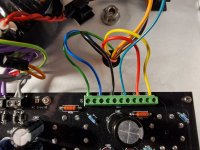
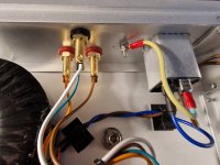
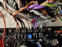
See the photos for how to connect the output transformers. The thin green wire connected to GND goes to the common output terminal together with the 0/white wire.


The 275 V is the correct one for the high voltage connectors.
See the photos for how to connect the output transformers. The thin green wire connected to GND goes to the common output terminal together with the 0/white wire.


I got all connected and I started the process for the first power on. First step it passed, was i supposed to check the right side too? Not sure which points.
I went to step 2, plug in the valves and turned on the power, it blew R429. I am stuck, not sure what i am supposed to look for the error I made.
I noticed the LEDs did not light up on either side, step 1 or step 2. I am guessing I put them in reverse. Can I replace them with any LED or there is something special about the LEDs listed in the BOM?
The LEDs were in reverse position, removed them, checked them and put them back in the correct orientation, i have to pay more attention to LEDs, this is not the first time making this mistake. I had a spare 10R 0.6W to replace the blown resistor. I checked the back of the PCB for shorts, and I dont see any. I didnt try to power the board again until i get some feedback on what else should i check. I would really appreciate some help, my knowledge in electronics are very basic, trying to learn as I go.

Also, I think the EL34 sockets are installed the wrong way. The notch on the sockets should be toward the front of the board. I'm not at home at the moment, so I can't double check.
Yes! You are of course right.No, the alignment of the EL34 sockets is correct !
i turned those pots anticlockwise, maybe I didnt turn then enough, they are multiturn, correct? Is there a way to check if I turned then enough before powering the board or at least before plugging in the valves? I really appreciate you guys helping a NOB like me.
Probably this was the problem. I probably turned just one of the pots and I missed the other one. The entry fuse blew, replaced that one too.Maybe you have too much bias. Those blow when you have too much current across resistor.
I installed the LEDs in the correct direction, now they light up. Replaced the 10R resistor, double check the PCB for shorts and didnt find any.
The voltages are close to the specs and I was able to install the valves and nothing went up in smoke. now I am at the bias adjustment step, I am waiting for the valves to warm up, I figure I will give them about 10 min
Unfortunately my saga continues. While checking currents I run into a problem when I probed the current across the R305/R405. I got a spark and I fried the LEDs. I have a bunch of LEDs in my stock but I am not sure if there is anything special for D301/D302 or I can put any LED in this place. I didnt unsolder the Transistors Q301, Q302, possibly those are fried too.
Also, while measuring across R321/R322 i got about 80mA, looking at the instruction I should have 1.5mA
Another question, I noticed on the board there is NFB(negative feedback?) but looking at other builds I dont see anything connected to it and on the connection schematics is not mentioned at all, not sure what is the purpose for this.
I replaced the LED with some 3mm blue LEDs. They light up, Unfortunately when I get to step of splitter balance i cant go lower the about 45V. I guess those LED i have are not what i need and maybe the transistors are fried too. I placed an order for replacements. I hope this is all that I fried.
My friend Sarunas helped me out. I figured all out, those LED needs to be red, he helped on how to read those currents too, NOB mistakes. Now is time to give it a try for sound. Probably in the next few days
Today i tested for sound, it sounds nice, there is some hum and I know there is an adjustment for it. Thank you @tbaashus, @Sarunas and
all of you guys helping me out, I apologize for dumb questions I asked, now I know much more.
Thank you @tristanc for this very nice project

Here is my project, pretty much same as @tbaashus.
all of you guys helping me out, I apologize for dumb questions I asked, now I know much more.
Thank you @tristanc for this very nice project
Here is my project, pretty much same as @tbaashus.
Looks great!Today i tested for sound, it sounds nice, there is some hum and I know there is an adjustment for it. Thank you@ @tbaashus, @Sarunas and
all of you guys helping me out, I apologize for dumb questions I asked, now I know much more.
How much hum do you have? Can you hear it from a listening position?
@Eliad Your build looks great. Well done for getting over the issues. I hope you get the hum sorted too. Keep us posted.
I added the connection for NFB as some builders of the BH choose to not use ultra linear (or a differing %age of it) and instead wrap the whole amp in a feedback loop. Also I was copying the other group build schematic. A second reason to include it is the possibility of running the amp with balanced inputs. I’ve not tried either, nor will I likely ever do so.Another question, I noticed on the board there is NFB(negative feedback?) but looking at other builds I dont see anything connected to it and on the connection schematics is not mentioned at all, not sure what is the purpose for this.
@tristanc. This was a short test for sound, I was anxious to test it after all my adventures and stupid mistakes. I have few more things to clean up. First I need to connect the toroid shield to the ground, i wonder where to connect it to follow the star ground concept. I have a ground position right on the PCB board or should I connect it to the ground at the AC inlet? I also need to adjust the HT ripple filter which i didnt touch. I might also have to change the input cables.
With shorted RCA plugs at the input the hum is quite noticeable for few minutes and then it is dead quiet. With open inputs the hum is still quite loud. With the line preamp connected and with the volume at comfortable listening level (this amp is loud for my DIY Klipsch Belle) there is no hum.
If I understand this correctly, NFB could be used for the other side of a balanced input? That would actually be great for me. I have a very slow project for a line preamp which has a balanced design.
- Home
- Amplifiers
- Tubes / Valves
- Stereo EL34 Baby Huey Build Log - an "Engineer's Baby Huey"