It may be your PT has a well-balanced heater winding. Or the CMNR of a PP amp is cancelling it out already. The only way to be sure is to scope the output and/or the heater circuit. The way I’ve done it on a SE guitar amp is by attaching a scope probe to each heater connection, with the ground connected at the CT. Then set one of the channels to subtract from the other. The displayed signal can then be minimized by adjusting the humdinger until it is as small as possible.I am still wondering why the hum dinger pot doesnt seem to have any influence on the hum
Whether that is any better than using your ears is debatable. For my BH build, I haven’t adjusted the humdinger from its factory set position (that I assume is middle).

@tbaashus, i came in the possession of bandolo Baby Huey PCB version. Reading that thread I noticed you build one yourself. What is your impression when you compare it with current engineer version? For the bandolo version I dont have the power supply PCB.
Reading @bandolo83 Baby Huey thread i see they came up with the concept to use DC to power the filament, I am thinking to try it for my own engineer build, I have a suspicion using DC for the filament will reduce hum. I have a cheap Chinese tube amp and it uses DC to provide filament power and it is very quiet, no mains hum. I am thinking my hum is from the filaments because it is mainly the 60Hz hum which is my understanding it can come from the filaments and usually is not related to ground loop which is usually 120Hz.
Another thing I noticed when reading about vacuum tubes, it is usually recommended to delay the B+ power to give a chance for the filaments to warm up, apparently this can help with the life of the vacuum tubes.
Please take all of these statements with a grain of salt, I am not an electronics engineer, is just a hobby and i try to learn as i go. As i read i can certainly come across some inaccurate information which sounds good to me but it is completely wrong, I dont have the knowledge to discern what is pseudoscience. Hopefully with time i will get better.
Finally I also made some progress in building Baby Huey. And first tests also were made.
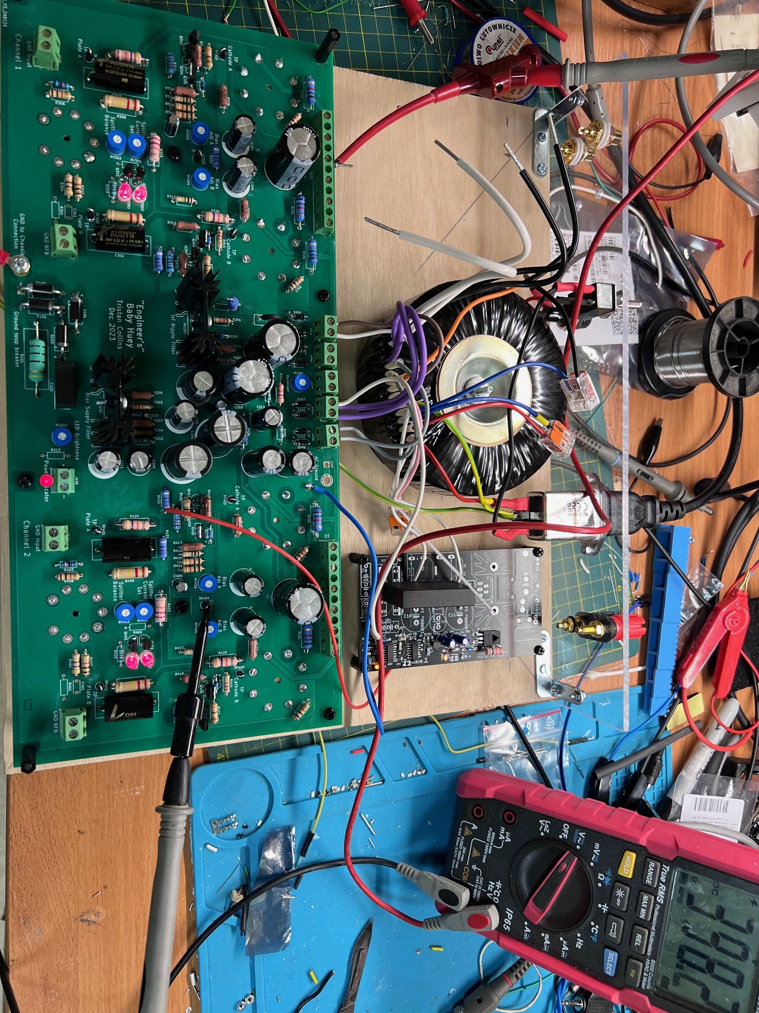
All voltages without tubes are as specified. B+ is 398V. Then I installed tubes just for one channel. Again everything looks fine. Bias was set to 45mA and B+ dropped to about 370V. After installing tubes for second channel something went wrong. After few seconds B+ voltages started to drop and I was not able to run both channels simultaneously. Current consumption was too big, Q201 gets hot, also R201:

Decided that something is wrong with Q201 (FQPF8N60C) and changed it to alternative SPP17N80C3 but situation was the same. Still current consumption was too big for both channels. Then I readjusted bias for both channels from 0 slowly increased it to about 41-42 mA. And now it works for few hours just B+ dropped to 350V and I am not sure if this is correct. Transformers are from Toroidy.pl and tubes TAD red base and Genalex Gold Lion.
Now should find out how to make more convenient jig for testing because still do not have a case for amp.

All voltages without tubes are as specified. B+ is 398V. Then I installed tubes just for one channel. Again everything looks fine. Bias was set to 45mA and B+ dropped to about 370V. After installing tubes for second channel something went wrong. After few seconds B+ voltages started to drop and I was not able to run both channels simultaneously. Current consumption was too big, Q201 gets hot, also R201:
Decided that something is wrong with Q201 (FQPF8N60C) and changed it to alternative SPP17N80C3 but situation was the same. Still current consumption was too big for both channels. Then I readjusted bias for both channels from 0 slowly increased it to about 41-42 mA. And now it works for few hours just B+ dropped to 350V and I am not sure if this is correct. Transformers are from Toroidy.pl and tubes TAD red base and Genalex Gold Lion.
Now should find out how to make more convenient jig for testing because still do not have a case for amp.
Attachments

Looking good. It does sound like too much current is being passed. That drop in B+ is a bit of a worry. It looks like you have all the right kit etc - perhaps check for stray wire strands / solder bridges etc. Maybe remove the valves and check voltages against mine at the same stage (on github), then add valves to one channel and check voltages. Then remove. Then add same valves to the 2nd channel and check. Eliminates a bad valve / see if both channels behave the same or if one channel is the culprit.
Current consumption looks ok for both channels. It is about 85mA or 0.85V across R334 and R434.
I’d expect the total current consumption to be ~90mA for both channels. ~40mA for the EL34 cathode, ~5mA for the screen and ~5mA for the driver.
If you’re getting 85mA for each side then the EL34s are biased too hot.
If you’re getting 85mA for each side then the EL34s are biased too hot.
Apologies - my brain was somewhere else. I forgot to multiply the EL34 current by 2... Yes, ~90mA across R434, ~4.3mA across R433, ~11mA across R432.
So ~105mA per channel, 210mA for both channels and what you should get across R208. So ~5V drop.

So ~105mA per channel, 210mA for both channels and what you should get across R208. So ~5V drop.
By the way 275VAC or 330VAC you used for HV secondary? I think tbaashus also had about 350V with 275VAC.
- Home
- Amplifiers
- Tubes / Valves
- Stereo EL34 Baby Huey Build Log - an "Engineer's Baby Huey"