I am curious about measurements with full power. I predict that it will not work. Or I have to go back to university again...........
Dr. Frost: http://www.diyaudio.com/forums/chip-amps/206591-tda7294-power-transistors-amp-tda7293-come-also.html
Dr. Frost: http://www.diyaudio.com/forums/chip-amps/206591-tda7294-power-transistors-amp-tda7293-come-also.html
Math. 8 Ohm x 50 Hfe = 400 Ohm.
f 3 dB = 1/2 Pi RC = 1 / 6,28 x 400 x 100 uF = 4 Hz.
Ok Should work.
f 3 dB = 1/2 Pi RC = 1 / 6,28 x 400 x 100 uF = 4 Hz.
Ok Should work.
One could swap out the 100uF to become 1uF and then measure the F-1dB frequency when driving an 8r0 dummy load. See if it changes when testing into a 4r0 dummy load.
Then try 10uF and see if it does go down one full decade into both loads.
Is it reasonable to assume it would go down another decade when returned to 100uF?
Then try 10uF and see if it does go down one full decade into both loads.
Is it reasonable to assume it would go down another decade when returned to 100uF?
You don't hear distortion on an ..... AC/DC song?distortion i cant hear on my test song(hells bells).
😱 😱 😱 😱 😱
Have they gone soft or what? 😀
zanden30 I think you are mistaking something really.
That cap is not even needed there I think.
The current comes from the driver chip, not through the resistor.
Ahh last page didn't come in yet.
But still don't know if the cap is even needed at all. Or it acts as filter.
That cap is not even needed there I think.
The current comes from the driver chip, not through the resistor.
Ahh last page didn't come in yet.
But still don't know if the cap is even needed at all. Or it acts as filter.
Last edited:
You don't hear distortion on an ..... AC/DC song?
😱 😱 😱 😱 😱
Have they gone soft or what? 😀
bell sound on begining is very nice for ear check distortion, for me at least
What good does the output stage do really? The LM3886 can deliver 11 amps by itself. What kind of improvements do you get with this extra external output stage?
i almost always use 4r speakers ,and have cheap transformers available local, but 28+28 or 30+30vac . i dont even aim for more than 5 amps out actualy
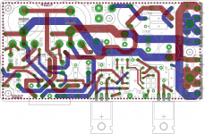
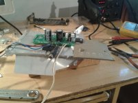
if this crap board up measures good,i will order few of boards on picture down and that should measure/work better
if this crap board up measures good,i will order few of boards on picture down and that should measure/work better
Attachments
Last edited:
i expect better or same distortion, 100w output, 24/7 operation,all loads,4r work on relative high +-40v dc. oh yes and if needed only lm can be used with only place wire on place of resistor,so no need of different board and always can have components on stock.
sort of all i could/will need in one board and parts can be left out.
do i ask too much?
sort of all i could/will need in one board and parts can be left out.
do i ask too much?
The LM3886 is capably of 0.005% distortion, pretty low.
The PSRR is excellent but you output stage has almost zero rejection meaning ripple will mix with the sound and create distortion. Your best move is to make a perfect pcb for the chip itself and to have proper decoupling and ground planes on the pcb. A critical spot when you have a pcb and power signals is the grounding scheme. A small mistake in the pcb can change the distortion from 0.005% to 0.1%.
The PSRR is excellent but you output stage has almost zero rejection meaning ripple will mix with the sound and create distortion. Your best move is to make a perfect pcb for the chip itself and to have proper decoupling and ground planes on the pcb. A critical spot when you have a pcb and power signals is the grounding scheme. A small mistake in the pcb can change the distortion from 0.005% to 0.1%.
NS specifies the thing for only 68W @ 4 Ohm.
The ChipAmp clips with 7A (see specs). If you are lucky @ 11A, but do not count on it. So you need the boost transistors!
P = I^2 x R = 49 x 4 = 196 W.
P RMS (sinus) = 1/2 of that so 98W. But you are working on the limits ==> boost really necessary for 100W with low distortion. Also for heat dissipation.
Last edited:
From the data sheet of the LM3886:
Over-Voltage Protection: The LM3886 contains overvoltage protection circuitry that limits the output current to approximately 11Apeak while also providing voltage clamping, though not through internal clamping diodes. The clamping effect is quite the same, however, the output transistors are designed to work alternately by sinking large current spikes.
NS specifies these for a cold chipamp at 25°C and driving a resistive dummy load.NS specifies the thing for only 68W @ 4 Ohm.
The ChipAmp clips with 7A (see specs). If you are lucky @ 11A, but do not count on it..................
Those numbers reduce when the chip warms up and spike makes them even lower, particularly when the loading is reactive.
A warm 3886 driving a mildly reactive speaker load cannot pass adequate current to avoid current clipping of transients.
That's why one hears the 3886 becoming "loud" in a not nice way when compared to a 50W discrete power amplifier that is not current crippled.
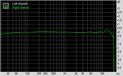
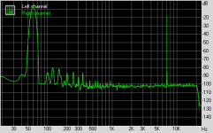
here are measurments, i tested it with 4r speaker and machine headphones as i dont have big enough resistor for this
Attachments
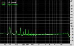

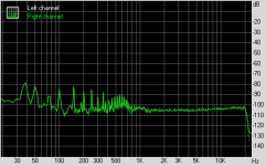
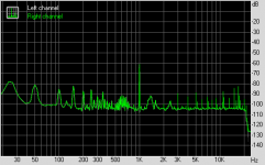
You have > 0.1% distortion at unknown power = 20 times worse than the chip alone
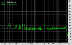
At 10 kHz ?? Horrible I should think.
At 10 kHz ?? Horrible I should think.
Last edited:
If your diodes are plain diodes (not LED's) you will end up with a class B stage which by nature is bad sounding, especially at high frequencies.
the plot shows third harmonic @ -40dB relative to signal, that's 1% 3rd
the 2nd is at -64dB and 5th is at -56dB
Those three harmonics add up to 1.22% distortion.
That is worse than attrocious.
the 2nd is at -64dB and 5th is at -56dB
Those three harmonics add up to 1.22% distortion.
That is worse than attrocious.
i think i need to order proper boards,proper high power resistor and proper measuring gear.
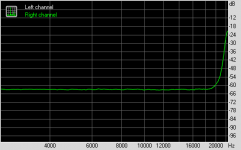
measurment was on max out, need resistor to check how much wats exacly but probably little over 100. i am concerned only about that peak in fr
measurment was on max out, need resistor to check how much wats exacly but probably little over 100. i am concerned only about that peak in fr

- Status
- Not open for further replies.
- Home
- Member Areas
- The Lounge
- stereo chipamp channel separation