Hi, personally I don't like the path it took.
If I were to do it, I would, in order of preference-
1) Use star ground. My preamplifier projects benefits from this, none of them are noisy done that way. It does not look pretty (but better than Sakuma's 😀) and it does the job well.
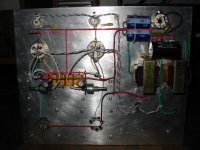
2) Use "T" style bus. If you'll look underneath the posted picture of my 300B amp, you'll notice (aside from the blue capacitors in the wrong direction 😀) how I employed the bus. My 300B runs on AC filaments, and you will not hear any hum with your ears within a foot from the speaker cone.
re: shield, I normally use salvaged two-conductor shield wire from old heaphone units. I find them easy to work with and good for the application. So, I have never used a coax. I think the method you mentioned is a practice for interconnects.
Cheers!
ps.
What amp is this?
If I were to do it, I would, in order of preference-
1) Use star ground. My preamplifier projects benefits from this, none of them are noisy done that way. It does not look pretty (but better than Sakuma's 😀) and it does the job well.
2) Use "T" style bus. If you'll look underneath the posted picture of my 300B amp, you'll notice (aside from the blue capacitors in the wrong direction 😀) how I employed the bus. My 300B runs on AC filaments, and you will not hear any hum with your ears within a foot from the speaker cone.
re: shield, I normally use salvaged two-conductor shield wire from old heaphone units. I find them easy to work with and good for the application. So, I have never used a coax. I think the method you mentioned is a practice for interconnects.
Cheers!
ps.
What amp is this?
Its my design. 12AY7parallel - 12AT7 cascode tail CCS LTP - KT88 PP triode. Unfortunately I use a chassis from an older amp, that has a nice to look at tube placement, but output tubes and inputs are located extreme left and right. I am afraid it has potential to buzzzz. I will sketch a T in a minute so you can tell me a new opinion.
T bar.
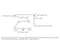
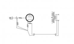
Here it is. Better? As for the coaxes, my concern is, that if input interconnects are going to be grounded at the input RCAs connected with the front portion of the busbar, they must not get to the first stage gnd also, it looks like a loop. So I think its better I attach the internal coax shields at the rca rings only.
PS. Thanks SY!
Attachments
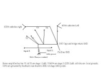
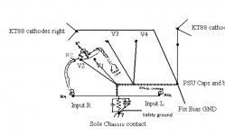
SY said:Assuming V1 and V2 are input tubes and V3 and V4 are drivers, I'd do it like this:
SY, in your proposition, the solid copper portion can be safely restricted to the picture's bottom and right 90deg angle part, and the other contacts come with cables, short of sub stars?
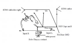
In the attached pic is Arnoldc's T method proposition for reference.
Attachments
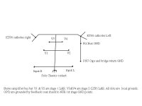
Better?
Yes, but still not optimum. I've highlighted the thick copper bus from my earlier drawing.
Attachments
I should add, you want some form of groundbreaker between the amplifier ground and the safety (earth) ground. I show a resistor (27 ohms is a safe value), but it's been pointed out that this could compromise safety. These days, I use a 27-33R resistor paralleled by 1nF and two diodes (in parallel, each "facing" the opposite direction).
Others have used groundbreaking switches or plug assemblies, but those will then rely on the ground integrity of other components in the chain and make me nervous.
Others have used groundbreaking switches or plug assemblies, but those will then rely on the ground integrity of other components in the chain and make me nervous.
Hi Salas, I'd favor the short bus by Sy. Won't look as neat, but might be better.
ps.
Sy, I always have my circuit ground floating. Am I violating any safety rules? Sorry for being lazy... 😀
ps.
Sy, I always have my circuit ground floating. Am I violating any safety rules? Sorry for being lazy... 😀
SY said:I should add, you want some form of groundbreaker between the amplifier ground and the safety (earth) ground. I show a resistor (27 ohms is a safe value), but it's been pointed out that this could compromise safety. These days, I use a 27-33R resistor paralleled by 1nF and two diodes (in parallel, each "facing" the opposite direction).
Others have used groundbreaking switches or plug assemblies, but those will then rely on the ground integrity of other components in the chain and make me nervous.
A CL60 thermistor is known to do the job, and do it well.
Magura 🙂
I will go SY, so to keep the buzz gremlin away, without aftermods hopefully.
I had a 15 Ohm with 1nF there in the older amp. I will retain it. I will add a couple of 1N5401 3.0 A diodes mounted 69 so whatever more than 0.7V difference trips my house mains earth sensing circuit breaker.
Should I ground the coax from each channel input to first stage only at the RCA ends?
I had a 15 Ohm with 1nF there in the older amp. I will retain it. I will add a couple of 1N5401 3.0 A diodes mounted 69
so whatever more than 0.7V difference trips my house mains earth sensing circuit breaker.Should I ground the coax from each channel input to first stage only at the RCA ends?
I will add a couple of 1N5401 3.0 A diodes mounted 69
Exactly what I was thinking, but I couldn't think of a more elegant way to put it. As a moderator, I have to restrain myself on occasion.😀
Arnold, the bus doesn't have to be physically short, I just was lazy and didn't want to redraw much. In the Red Light District amp, with a similar topology, the bus is about 18 cm long, terminating at a ground plane near the input on one end and the power supply common on the other.
Think of what happens if you have something HV short to chassis and ask if this will cause a breaker to blow or what will happen to exposed supposedly-safe points like input jacks and speaker terminals.
SY, I will make it tomorrow. AC heaters 50V floating twisted wires first , then the buss and gnds, filaments aglow check, cascode CCS little board in with LM337 -V on its tail, fix bias board then, again with LM337, -V grids check, then the circuit, maybe in a couple of days is going to sing again, with more resolution. Sadly LED bias wont apply well in my first stage. RC for me. And I will see about attaching both or one end of the Mogami input coax in practice. Quiter wins.
Thanks a lot for now...and if it will dare to buzz I will voodoo it!
Thanks a lot for now...and if it will dare to buzz I will voodoo it!
SY said:
<snip>
Think of what happens if you have something HV short to chassis and ask if this will cause a breaker to blow or what will happen to exposed supposedly-safe points like input jacks and speaker terminals.
I hear you, thanks for kicking my butt 😀 Will do exactly what Salas would do 😉
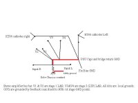
Salas, use the coax to ground-reference the output transformer secondary at the input socket end. I think coax is a great way to run the feedback loop, and the idea of applying the feedback directly across the input stage cathode resistor is also a good one.
A couple of comments. I wholeheartedly endorse the diode ground-breaking idea. I'm making that my new norm. In fact, right now I'm refurbishing two HK Citation II amps and the only hole I'm drilling in the chassis will be the one for the combined ground bond and diode bridge mounting, as I reconfigure their less-than-optimal original grounding scheme.
I recommend beefier diodes than 3-amp devices however, since safety is at stake. You want something that will decisively and reliably open the fuse or breaker in a fault event. I suggest using those four-diode bridge rectifiers that come in one rectangular block with four terminals coming off the top side. Look for 25 or 35 amp bridges. PIV is not important, and can be 50 or 100 volts since the most any diode should see in reverse voltage is 0.7 volts. If you wire the two AC leads together, and the two DC leads together, you will have four diodes in a double-69 position (hey, I didn't start this). Two up and two down. This gives you redundancy in case one diode opens. I take some comfort in knowing that this arrangement could pop the line breaker at the service panel in case the fuse didn't do its job. These rectifier bridges can be found surplus at very cheap prices. When you find a bucket of them for $0.50 each at the surplus place, buy a lot of them for future ground breaking duty. Just be sure to check each of the four diodes before use.
The value of the resistor that goes across the diodes from signal ground to chassis ground is an interesting question. If you use a beefy 2.7 or 4.7 ohm resistor as some suggest, the resistor could conceivably contribute current in a useful way to blowing the fuse during a fault. But these low values may still allow a hum loop. The 27 ohms suggested here would probably break most hum loops, but has less value for fault protection, and unless it's very large might go open in a fault anyway. It should not be relied upon for fault protection. When I use a 25 amp or 35 amp rectifier bridge as a loop breaker, I wire a 10K to 100K carbon comp resistor across the diodes to serve as a gentle ground reference against any leakage or static build-up in the amp insulations. The diodes will never allow the two grounds to drift apart by more than +/- 0.7volts anyway. I forfeit any fault current protection that the resistor could dubiously offer and allow the diodes to do it all. The value is not critical, but I'd like it much higher than any ground loop resistances to preclude any possible hum path. I may be missing some other rationale for a moderate value like 27 ohms, and if so, please enlighten me. I then parallel that resistor with a 1000pF mica for RF grounding.
- Status
- Not open for further replies.
- Home
- Amplifiers
- Tubes / Valves
- Stereo BusBar OK?