Some thoughts
I just recieved some product sample and literature from 3M about the Vikuiti line of lighting films.
I recieved 1 sheet each of the following
ESR
BEFII 90/24
BEFII 90/50
TRAF
My plan is to set them up similar to how the diagrams that they sent show and see what kind of light output I can get from a couple different light sources... I'll keep you guys updated. Hopefully will get my LCD early next week and can start working with it then. 🙂
This is just kind of grins and giggles stuff, but:
How would using a couple of these (FC27/s65) be?
They are: 10,000 hour life
6500 Kelvin
2800 Lumens
and only 42 Watts.
If you did a cluster of 2 or 3 of these in the center of a spherical reflector, that should give you some decent light, I would think. Any thoughts out there on this?
How would using a couple of these (FC27/s65) be?
They are: 10,000 hour life
6500 Kelvin
2800 Lumens
and only 42 Watts.
If you did a cluster of 2 or 3 of these in the center of a spherical reflector, that should give you some decent light, I would think. Any thoughts out there on this?
Yep should do quite well. Thats a good spec light. Very cheap too is that $13 each.
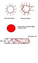
The general problem with fluorescent type bulbs is they are not a point source lamp but a multi point source. This makes them ackward to use in a reflector but a reflector does help.
One way to gather more of a fluorescents light is to make our own lamp.
Say a 4 foot tube tightly wrapped with reflective tape to keep the light inside the tube and then a mirror at one end and a clear glass exit port at the other end. In the drawing, light going forward is red, light going to the left is blue and becomes going forward light after reflecting from the mirror.
Attachments
correct me if im wrong but arent those smaller versions of LOAs? becuase i've seen LOAs that size .
Remp, would a 4 foot tube be too long? when light travels doesnt it lost its luminosity? since these lights generate no heat (practally) i think they can be very close to LCD,but im no pro. and where would one buy a reflector for this project?
-JimmY-
Remp, would a 4 foot tube be too long? when light travels doesnt it lost its luminosity? since these lights generate no heat (practally) i think they can be very close to LCD,but im no pro. and where would one buy a reflector for this project?
-JimmY-
I was thinking the reflector would have to be made. I was thinking a piece of formed aluminum or stainless steel, bent around a collander or something similar. Then, using a Dremel or other high-speed rotary tool to polish to a high sheen.
Another thought would be to enclose each bulb in its own reflector, with a fresnel cut to size and mounted on the front (basically recreating a floodlamp and similar to remp's suggestion, but it cuts down on distance the light travels, as the fresnel can be mounted right at the tip of the bulb).
Then place these bulbs (2 to 4 should do it, at this plan) behind another fresnel to diffuse the light evenly across the screen.
okay first of all there is a HIGH probability that i am about to say something incorrect -- so feel free to tell me im a retard.
i dont know if you can just reflect the light from a fluorescent back into or through itself because although it gives off light, the tube itself is opaque.... any thoughts?
i dont know if you can just reflect the light from a fluorescent back into or through itself because although it gives off light, the tube itself is opaque.... any thoughts?
Thank you for asking that. I was thinking maybe I needed to clarify what I said. Little or no light would pass through the bulb (test this by holding a flashlight to a fluorescent and see how much light you can see on the other side). My thought with the reflector is to use a semi-circle or elliptoid so that the light is reflected back (for the most part) above, below, or to the side of the bulb. Some light would be lost by going back toward the bulb, but a significant amount should be broadcast 'ahead' of the bulb.
This is why I thought building floods out of the individual bulbs, then harnessing the combined light through a diffuser would yield a good result (although the individual fresnels can probably be eliminated, upon further thought). See the ascii art below for my thought on how it may work(with a 3 bulb setup):
Legend:
"(" = reflector
"O" = light source
"|" = fresnel
"<" = light beams
"=" = corrected light
"#" = LCD panel
(O < |= #
(O < |= # <
(O < |= #
What I think will happen is:
Light will move forward (not necessarily directly ahead, though, but in a forward direction) as it leaves the bulb. What light does not move forward will hit the reflector and either be redirected forward or hit the bulb. The light that hits the bulb will be partially absorbed and partially reflected (the beauty of bulbs being nearly pure white). the reflected light will hit the reflector again, but at a different, complementary angle than it did the first time (because of the round shape of the bulb). This light will then be redirected forward or back at the bulb in the same process, until the light is either absorbed by the bulb or reflected forward. The fresnel will be directly in front of the three bulbs (with just enough space between the fresnel and bulbs, and the bulbs themselves to allow even distribution of light across the fresnel). This light will then pass through the fresnel, then through the LCD, at which point it will, depending on projector design, shoot out directly through the projection lense, reflect off a mirror to the lense, or some other design.
jvisaria
I think you are 100 percent correct. The light that comes out of a fluorescent could be easily reflected back where it would go through the glass as it did on its outward journey but then it would hit the phospher coating on the inside of the tube.
My thoughts were "some might get back in. In any case the tube is probably full of light already where the UV has activated the phosphers.
My guess is 50 percent is inside the tube. So then I thought if there is a percentage inside the tube that cannot pass through the phospher layer thats not very efficient so I thought OK they probably made it so it can get out. Therefor if it can get out it can get back in. But in anycase my design (if you can call it that) was a bit optimistic because the inside of the fluorecent is not so good at reflecting. Not like real mirrors.
I was kinda hoping someone would say hey that wont work but its given me an idea. Something like ever expanding the reflective tape out in a cone around the tube with a mirror on the back end to make backwards light turn around and go forward. Still using one or more straight tubes.
markm
I think your idea is great. At $12 a bulb thats only #36 + a homemade reflector and low running costs and all standard easily replacable bulbs. 42 watt bulbs x 3 = 126 watts electricity. You could add another few more bulbs if you wanted to and still be energy efficient. Coupling multiple sources together with minimum loss. Thats an interesting question. Some time ago Xblocker showed a German LCD projector that used 4 bulbs to illuminate each quarter of an LCD. Apparently it worked very well.
The 4 bulbs/reflectors hit a diffuser panel to even out the light.
How can we collect as much light as possible from a Fluorescent tube system
Do we go for one or a pair of LOA. Its been tried before and found a little short of enough power. But going into the backlight with its polarization recycling, there may be enough light.
Do we try out multiple bulb type fluorescents. Put 3 or so in one reflector, or in individual reflectors and then combine them.
Could we think of some way to immerse a fluorescent system in a liquid lightguide. If so would it work out cheap enough to build.
Should we get 10 or 20 CCFL tubes and arrange them to direct their light into a lightguide.
Should we concentrate on high output LED units.
One of the light sources that intriques me is these new sulphur lights. 100,000 lumens virtually unlimited life. Sunlight colour temperature and no electrodes. Its energised by externally applied energy using no wires. Around the $1000 mark for a 500 watt unit. The bulb is spun by a small motor. Enough power to light a factory they say.
www.thekrib.com/Lights/sulphur.html
There is a French company who have developed high power light beam using fluid.
http://www.illuminator.megalux.com/
These units would be far too big for us, but can we think up how to do it on a smaller scale.
Maybe its as simple as surrounding a fluorescent with a plastic light guide and hopefully collecting a good deal of the radiated light. One thing is for sure. Relatively cool cheap low operating cost light is there. All we have to do is collect it.
Remp:
Right now, it looks to me like one of the best backlight modification options comes with a long, cyllindrical tube bulb (or several of them in series) in an elliptical reflector with the second focal point the edge of the LCD panel's backlight optics. That seems simple, it seems cheap, and it seems easy to build.
The main problem is the cooling system, so we might have to put some heat-blocking glass in there.
Even though I've always been a large proponent of the LED-method, until I test it out when my LED's come in, I think I'll just have to be more realistic and look into halogen/MH bulbs.
--Clint
P.S. Looking at my picture again, there's really nothing to stop us from making the ellipse curve around more, and it will only save us more light. That reflector could almost curve around and meet the panel.
P.P.S. Ah. One more edit. If we had the problem with heat, we *could* make the blue backlight in the picture just a sheet of acryllic the width of the backlight, and make it a simple, easy-to-cut light guide, and in that way remove the LCD from much of the close-contact heat.
Attachments

I have been reading a lot about increasing the backlight intensity and everything I have been reading says that using a light guide is not very efficient, too many losses occur. Everything says that a direct lit LCD is much brighter than a conventional side lit Light guided model. The cost of this is much more depth is required. However we do not really need to be concerned with the depth, anything has to be better than what we currently have available using MH or other means of lighting.
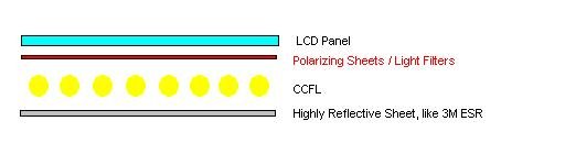
I think that we might be able to use multiple cold cathodes mounted with 3M BEF or similar film and then mount them directly behind the LCD. Behind that a very reflective mirror would be installed as a reflector.
This method has had success for at least one company, Litemax in making their LCDs readable in direct sunlight. I guess their LCDs boast up to 2400nits brightness compared to the typical 200 - 250. It appears that this is the model that they are using... hopefully my panel will be here soon so I can do some real testing.
I am going to attempt using the 3M sheets that I have to see what kind of brightness can be realized with and without the sheets to see if they are worth their extra cost, because they are not cheap things at all.
Attachments
Forgot to include the link to Litemax's success.
http://neasia.nikkeibp.com/nea/200111/peri_152143.html
I think this company may have been mentioned earlier by somebody as I seem to remember this website
http://www.litemax.com.tw/
Worth a further look though.
http://neasia.nikkeibp.com/nea/200111/peri_152143.html
I think this company may have been mentioned earlier by somebody as I seem to remember this website
http://www.litemax.com.tw/
Worth a further look though.
Wow.
haha. Check this out. 🙂
I really like the CCFT array idea. Using this ccft
you can fit 72 of them in the 8.5" space behind a 14" LCD panel. They're 3 mm in width, which is .118". That goes into 8.5" roughly 72 times. 72 * $2.75 = $198 (not to mention inverters to drive all of these... but it would probably be easier to make your own inverters). Especially if you used the polarizing recycling optics that Crash mentioned.
If these things are only 3mm in width (2.6mm for just the lamp I believe, maybe smaller), then we might be able to still fit this in the normal space behind an LCD, and not even mess with moving the boards around.
I feel like our options have been expanding so rapidly over the past couple days.
--Clint
I really like the price of those CCFTs. I keep seeing a price of about 13 dollars each w/ inverter.
I wonder if I can find a diagram of an inverter that I could build to drive multiple lights?
Depending upon the specs of this light it probably would not take that many bulbs.. perhaps as many as 12 would be enough. You must remember that space is needed for cooling of the bulbs and light must easily be reflected around the bulbs and back into the LCD or you lose too much efficiency for it to be worthwhile. Also the light that is reflected back from the polarizing sheet must be able to travel to the mirror and then back to the sheet in another spot.
I think that some modification of the electronics behind the LCD may be needed but maybe not. This method would require the removal of all of the current backlight/lightguide assembly and a new assembly attatched so it is possible that we would not have to disturb the electronics at all. Have to play it by ear I guess.
Thats great information you guys. Bit more forward thoughts. Just a question, do you think we should be aiming at leaving the LCD and its films if any in place and go into the edge of the lightguide. Reason. So guys can take a LCD monitor, remove the CCFL system and install a new higher power light package without touching anything else.
Remp I am concerned about how well we can focus the light onto the lightguide. If done properly I believe that it would work, and would likely be bright enough for most situations. The optics confuse me though. 
Crash
I read you.
Here's a thought for the day. A typical CCFL runs on about 500 volts and draws 5ma
watts = volts x amps = 500 x 0.005 = an incredibly low value of 2.5 watts. Thats for one tube. If it has two the backlight assembly draws 5 watts. Be a bit more in total because of losses in the inverter. But thats not a lot of power.
Hanclint0 has found a site that sells CCFL tubes complete with reflectors and lead wires with a plug for only $2.75 each.
You can run more current through a CCFL at the cost of reduced lifetime and of course uses more energy. In a laptop that would be important but in a mains powered unit like we have not so important. Even the reduced lifetime is not so important because we don't have the projector on all the time like probably happens with LCD monitors in an office situation, or even at home.
So what might be possible is a number of CCFL units, pushed harder than normal to get more light.
I figure the LCD manufacturers have gone to edge lit lightguides because they then have unobstructed space for films and diffusers and reflectors.
It might be possible to get hold of 10 or 20 LCD lightguides, stack them all behind the panel, power each lightguide with 2 or 4 hard driven CCFL's and still be able to use the 3M type films. That would need a lot of space behind the panel which is probably not available but the stack could be to one side of the panel and the final high power output delivered to the LCD regular lightguide.
Hanclint0 has found half the deal with his cheap CCFL units.
I know there is probably some kind of diminishing returns law that might stop that working but its definitely a possibility. I need to find some LCD lightguides.
I've got my panel.. Fedex man brought it today.
It is powered with 3 CCFLs per side for a total of 6CCFLs. These are sitting next to a lightguide and I get really really great light output. I am going to relocate the controller so I can more easily work with the backlight. Currently it is hard to play with everything. This panel looks like it will be really nice to work with because there is not a single board or anything located behind the LCD. Everything is off to the side, except for the controller. It is attatched with a big 40 pin ribbon cable so I am not worried about messing that up.
I am going to see what I can do with this thing now.. should be interesting.
Also, talking about the LOAs(going back a page or two in the thread), did you see the thread where I mentioned my SGI screen? If so, did you read my thoughts on how to get the light from between the coils of one of the twist bulbs? Anythoughts on that?
- Status
- Not open for further replies.
- Home
- General Interest
- Everything Else
- The Moving Image
- DIY Projectors
- Step into the Light.....