Bitbyter
You are right that sandpaper will act to diffuse the light.
The right way is to laser cut or silk screen a pattern on the side but for a start fine sandpaper works and we can use a 3M BEF film to straighten the light beams up.
But I do agree with you. Its just that we dont have all this very special optics tools so we have to think up simple alternatives.
As we go along we should get better.
ok
ok this might not be going along with the thread, but i went to walmart today and looked at all the different types of light bulbs. I found a halogen with about 1600 lumens, i dont remember the watts, but it said it lasted 5 years.. Maybe im wrong but i thought these dont produce much heat either.. So in theory couldnt we put 3 or 4 of these inside of a projector?
ok this might not be going along with the thread, but i went to walmart today and looked at all the different types of light bulbs. I found a halogen with about 1600 lumens, i dont remember the watts, but it said it lasted 5 years.. Maybe im wrong but i thought these dont produce much heat either.. So in theory couldnt we put 3 or 4 of these inside of a projector?
Heat has to be taken out of a MH beam same as for regular projection which is not what we want but its a start. Did you see the heat block in my drawing. I know that wil need a fan but the line is
Get it going with regular light
Improve it to a high performance.
That alone is good enough for guys that buy LCD monitors and it saves them breaking the flex cable
Then when a regular light source is powering the projector then we start on using lower heat lights such as LOA white laser or something.
I can buy a 1.5 amps 8 foot flourescent tube that puts out 12000 lumens for $290. Not quite economic at the moment but getting closer. CCFL will soon be gone as they are starting to use EE lights. So we should be able to get them cheap enough for a 10 or 20 bank.
EE are flourescent lights laid out flat. With special low loss glass and about 20 times more expensive than CCFL tube but lots more efficient. About 1/4 battery drain for same light.
This shows Teflon AF which is also an excellent lightguide.
Costs about $1 a foot is sample lots. Or you might be able to get some samples for free. Various diameters. There is a place in Canada that sells it Proffesional Plastics I think they are called.
www.biogeneral.com/teflonaf.htm
Maybe we could get a bit and inject the light at the round end and sort of squash the other end so its long and thin.
Needs a polished glass stopper both ends to stop the water falling out.
Also the water is a form of heat stop but over a period hottish water will grow things and need replaced. Maybe some bleach would do.
You are really supposed to do this properly you know with a lens at the entry point closely matched to the acceptance angle of the lightguide etc etc but for us the converging light will go in OK.
You can always do the fancy stuff later. And its not expensive.
If the diameters are too small for the whole light and the squash at the other end maybe several lenghts would do. Reduces the fill factor quite a lot because 10 small round pipes always have a wasted gap between each pipe whereas one larger pipe has no waste spaces.
There you are Zardoz. Is that ok for your high power fibre optics system. Except its a water optics system. Nearly the same.
embeding
I wonder if it would be a feasible idea to embed the light source into a lightguide. Since the primary goal of this monstroucity of a thread is to gather the most light, I figure this is the most practical method.
To conquer the fact that placing a hot light source in a plastic will melt it, one may place a gass-filled insulator between the bulb, and directly in contact with the lg.
Something like this...
http://web.tampabay.rr.com/sweetfeet/LCD Ribbon.html
It's the second picture.
To shave some weight, and size, perhaps the lg could be more ergonomic with respect to the bulb shape.
(I don't know how to insert pictures into a post. Could anyone enlighten me? thanks)
Make a picture
Save it as .JPG or .GIF
Must be less than 100k
Must be less than 800 x 1200
Write your post first
Then select browse.
Find your picture
Double click it.
It will then display your picture address on your hard drive.
Do not review your post or you will loose your picture address and you have to do it again.
Click submit reply.
Teflon AF water lightguide
Zardoz has measured the light guide at 8 9/16 x 6 3/8 with the CCFL on the long side. It will be on the long side because a longer CCFL puts out more light. Light could equeally well go in the short side.
Assuming the thickness at 1/4 inch and for simplicity the short side at 6 inches the area of the short side is
6 x 1/4 = 1.5 square inches.
A tube with that area is
phi x R x R =1.5
r = 0.668 inches
diameter = 1.33 inches
So to a rough approximation a tube 1.33 say 1.5 inches in diameter will squash up to roughly 6 inches x 1/4 inch.
The light from the Metal halide will enter the 1.5 inch entry port ok.
Polished glass end stops.
I dont have any. For round tube I use any flatish lens that will be a good tight fit. For the lightguide end maybe a piece of glass cut to be a tight fit. Or gladwrap. Anything to keep the water in and transparent.
If that does not work out too well use the round tube. That does work well but as mentioned has a penalty of less light transmision than one larger tube because of the fill factor.
http://www.diyaudio.com/forums/showthread.php?threadid=8980
(backlight retrofitting)
Sorry about the previous post. I hope this went through
I guess what I want to say was that the idea started when Verbose Mustafa (spelling) discovered he can attached his LCD right at the opening of the projection lens, and projects a good image on the screen (wall?), so he wanted to increase the brightness of the backlgiht, by using LED.
IF you want to use LED ...
didn't abandon ship
Just a quick note, remp I took a measure of my backlight tube...about 1/16 inch thick, 8 1/4 inches of "active" tube.
Everything is on the burner for the moment, for some reason business just lit up in a big way for my PC company. It seems there is a taste in the market for the U Buddie computers, a little tiny (eansy weansy) PC. Xmas sales this year was a write off. Suddenly I dont have time to build my custom PJ box because folks are buying machines or getting their existing up graded. 😉 at least now I can recover from my gear expenses.
zardoz
Fiber optics cheaper than I thought
Here is one site I found but I have more get them later from my favorites. Dang now Im thinking about DIY fiber optic home lighting.
http://www.fiberopticproducts.com/danise/cart.pl?db=stuff.dat&category=fixtures
Here is one site I found but I have more get them later from my favorites. Dang now Im thinking about DIY fiber optic home lighting.
http://www.fiberopticproducts.com/danise/cart.pl?db=stuff.dat&category=fixtures
...
I was wondeing what any of you thought about my proposal in placing the bulb right into the lg. This would work even better in a liquid light guide. The LCD i'm using is a Sharp built Dell 1500FP
It has a native res of 1024x768- 15"- @75Hz
Anyway, it has a light guide with the etched side facing away from the rear of the LCD, and diffuses to an even glow on a slick white backboard- almost like thick glossy paper. There is also what seems to be a light polarizing film directly behind the LCD consisting of three layers. The light is provided by 2 horizontal CCFL's, place on the top and bottom sides of the lg. I guess this is a standard setup. I am wondering whether it would be usful to keep the polarizing layer in the final pj setup. WOuld it be best to fit it before or after the fresnel?
sweetrobot
I think your idea is good. Maybe a bit early. Lets get the light from a MH into the backlight first.
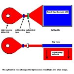
If the coupler is too difficult what about using a cylindrical lens. I have seen these on the net. You put in light and it comes out as a line. Some wood saws are using them now to show a line where the blade will be cutting for safety reasons.
I think your idea is good. Maybe a bit early. Lets get the light from a MH into the backlight first.
If the coupler is too difficult what about using a cylindrical lens. I have seen these on the net. You put in light and it comes out as a line. Some wood saws are using them now to show a line where the blade will be cutting for safety reasons.
What about...
I did some research on orthogonal parabolic reflectors and they seem like they might be REALLY cool for this sort of purpose. HOWEVER, a better option came to my mind while working on this....
What if we could get halogen tube (or string 2 or 3 of them together to get the edge width of our LCD panel), and then make an 2-dimensional eliptical reflector (kind of like a gutter with a half-eliptical shape), and focus the line-light sources onto a corresponding line on the LCD edge. We could even put flat mirrors at the edge of our little "gutter" reflector to get even more light back onto that line.
We wouldn't need the acryllic light guide as we could feed this focused line of light directly into the backlight optics of the LCD screen.
Anyone think this idea has potential? I think the main difficulty is in making an optically accurate reflector, but if Newton and Gallileo (sp?) could make decently optically accurate lenses, I think I can make a little elliptical reflector... I mean c'mon... it's not even parabolic.
Keep the wheels of imagination turning!
--Clint
Attachments

Remp:
Using a cylindrical bulb, it seems like a two-dimensional elliptical reflector would be better for getting a "fan" shaped beam of light into the edge of an LCD panel... I like your idea, but it almost seems like the light reflector would need to be orthogonal parabolic to get a good amount of light from a long MH bulb.
I'm still new, so I could be wrong. The 2d ellipse just seems really simple to me.
--Clint
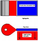
Clarifying picture
Here's a clarifying picture to show how my imaginary setup is different.
Doing it this way means that the light won't be horizontally parallel going into the backlight, but light coming from a CCFT isn't, so I don't think it needs to be for a normal diffusion pattern.
I'm really sorry if it seems like I'm slamming you Remp, because I'm not. I really like your ideas, and you're in my top-three most favorite people to read posts by on this board. I'm aiming more for a discussion of ideas rather than an idea bashing debate. Hope I'm not coming across wrong.
Respectfully,
--Clint
P.S. Note that I'm assuming our lamp is cyllindrical about a certain axis, and we can either mount 1 of them to be the length of the LCD panel or 2 of them end-to-end (not electrically, just with mounting hardware) to get a long cyllindrical light bulb.
Attachments
HanClinto
You stole my picture
Good on you mate. You are welcome anytime. Hey thanks for you kind words.
No the story is I don't care who's idea comes out on top. Its pushing forward that counts. Ok some of my ideas are completely impractical I admit that. The coupler is a good example. Too much like hard work when you can get a lens to do the job. Its all about solving difficult problems.
We are getting much closer now to being able to power up an LCD via the backlight position. And its only been a few days. A new LCD monitor would be an ideal candidate because it saves the risky work of lengthening the flex cable. Some don't have a flex cable so they could be illuminated by conventional means. Also its about trying to get more light through the LCD and some of these special films eg Brightness enhancing films and polarization films are all designed to do that specially in and around the backlight area.
This means if we can couple a 400 watt metal halide into the lightguide we might be able to drop down to a 250 watt bulb. Even better would be using something like LOA or high power LED's but I think that might be a little way off.
Since you cannot find this info anywhere else on the internet we just have to be the first guys.
What I do is post something I think will work then all the other guys think about it and somebody posts an improvement and somebody else improves on that and eventually we should get to something that works.
Tonite is Tim the tool man, then Crime scene then CSI then Star trek so I will be out for a while.
HanClinto
Quick note.
The 400watt Metal Halide in my drawing uses a round reflector. Lots of guys have used them. It is reliable and not too expensive so it makes a good light supply. It is almost a point source bulb with an arc length of 7mm so it needs a round to thin convertion
Quick note.
The 400watt Metal Halide in my drawing uses a round reflector. Lots of guys have used them. It is reliable and not too expensive so it makes a good light supply. It is almost a point source bulb with an arc length of 7mm so it needs a round to thin convertion
- Status
- Not open for further replies.
- Home
- General Interest
- Everything Else
- The Moving Image
- DIY Projectors
- Step into the Light.....