Hey Zardoz
You are the man.
How much comes from side E with the etchings and how much from side P the plain side. Are the lightguide edges smoooth. Is the edge where the CCFL goes in rough or smooth.
Any heat.
Do you think that ultrawhite sheet is to even out the light.
If you hold the lightguide up to the light it should be close to 100 percent transparent. And it may be tapered from one side to the other.
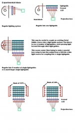
It may be possible to take a long fluorescent tube which has its electrical connections all at one end and wrap it with a highly reflective aluminium film thus keeping all the light inside the tube, and to extract the light at the other end.
This would enable the fluorescent tube to act as its own lightguide.
A bank of such tubes could provide high light output with a relatively simple light collection.
This would enable the fluorescent tube to act as its own lightguide.
A bank of such tubes could provide high light output with a relatively simple light collection.
observations
The etched side on the 10 inch panel lightguide that I have is approximately 400 "dots" per inch. The dimension of the guide is 8 9/16" by 6 3/8, the CCFL is mounted along the long side against a smooth surface. The guide is optically clear looking at it on edge. I have no ballast so most of my testing is by less than exact method. I am guessing that 75% or more of the light escapes through the etched side.
Yes I would agree the white sheet is to even out the light. On the LCD side there is mounted an "opaque" sheet of plastic, then the 2 polarizing sheets, then the LCD itself.
This unit uses a single CCFL so heat shouldnt be too much of an issue. I have found in my travels a few panels that have "tiny" muffin fans to cool them, most of these were double CCFL models so some heat is expected I assume.
There is a ridge cut out along the edge that the CCFL mounts to prevent "missmounting" also a couple of "keyed tabs" along the opposite length. All of these could be defeated I believe to test for "reverse opperation" I'm betting it will work like a charm.
The next panel I get I will try to get enough gear to run the backlight so we can learn more.I think there just might be some good results here. If we could alter a panel to accept CCFL's along ALL of the edges the light output would be MUCH more.
zardoz
tinyremp said:Hey Zardoz
You are the man.
How much comes from side E with the etchings and how much from side P the plain side. Are the lightguide edges smoooth. Is the edge where the CCFL goes in rough or smooth.
Any heat.
Do you think that ultrawhite sheet is to even out the light.
If you hold the lightguide up to the light it should be close to 100 percent transparent. And it may be tapered from one side to the other.
Wow
This thread is really starting to get interesting. Zardoz, does it look like there would be any way to just replace the CCFL with one of the LOA lights in an encloser that would direct the light through the side of the lightguide?? I am pretty familiar with the possibilities of using plexiglass as a lightguide because many people use it for computer moding. See this link http://metku.net/ and look at the mod titled router. THis is exactly what this guy is doing. This really ahs potential for decreasing the size of our projectors.
This thread is really starting to get interesting. Zardoz, does it look like there would be any way to just replace the CCFL with one of the LOA lights in an encloser that would direct the light through the side of the lightguide?? I am pretty familiar with the possibilities of using plexiglass as a lightguide because many people use it for computer moding. See this link http://metku.net/ and look at the mod titled router. THis is exactly what this guy is doing. This really ahs potential for decreasing the size of our projectors.
OHP Projection Panels
I know that OHP projection panels don't have backlights, but do they use the same polarization films as LCD Monitors?? If not I guess you could always build the enhanced backlight that we are talking about for these panels.
I know that OHP projection panels don't have backlights, but do they use the same polarization films as LCD Monitors?? If not I guess you could always build the enhanced backlight that we are talking about for these panels.
As I understand it an OHP uses it's double frezzie to effect the light polarization. On my laptop screen I discarded the polarizing sheets (those plus the frezzie = no picture) As for the lightpipe to replace the CCFL...uh...thats what we are trying to do here, or maybe augment the CCFL with a more powerfull one..or more of them. Either of these or all combined plus flipping the LCD lightpipe might just be THE answer. Hmm one lightguided LOA per side...flipped LCD guide...too bright to look at I'd bet...maybe too bright too close...is it possible to "wash out" and image with LCD?
It's all theory till we cook some gear 😉
zardoz (WE WILL invent the first COLD projector!)
It's all theory till we cook some gear 😉
zardoz (WE WILL invent the first COLD projector!)
edit previous post
"There is a ridge cut out along the edge (of the light guide) where it mounts to prevent "missmounting" also a couple of "keyed tabs" along the opposite length. All of these could be defeated I believe to test for "reverse opperation" I'm betting it will work like a charm."
Post must have been before my second cup of coffee this AM 😉
zardoz
Zardos
Great work on that lightguide.
Fresnels dont affect light polarization
Washout is only caused by insufficient contrast ratio in the panel.
Assuming all heat has been removed from light source you can run as much light as you like through a panel but eventually the colour filters will saturate. The main problem is insufficient contrast ratio which keeps the white parts of the picture and the black parts too close together. Even so you get a not bad picture with 50 :1. Better with 100 :1, and starting to get really good at 300 :1 or better.
Attachments
Here is an interesting article about using multiple LED or multiple CCFL
www.lumiled.com/pdfs/techpaperspres/IDMC_Paper.pdf
www.lumiled.com/pdfs/techpaperspres/IDMC_Paper.pdf
Re: old thread
Uh...harvey....why did ya post a cable thread in a light thread? misspost is my guess ?
zardoz
Uh...harvey....why did ya post a cable thread in a light thread? misspost is my guess ?
zardoz
harvey said:
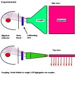
Coupler
The coupler that remp is talking is actually a light coupler. Designed to direct the light from the MH lamp into the side of the LCD backlights lightguide. It has nothing to do with cable couplers.
The coupler that remp is talking is actually a light coupler. Designed to direct the light from the MH lamp into the side of the LCD backlights lightguide. It has nothing to do with cable couplers.
Making a Coupler
Does anyone have any ideas on who to approach to have a customs light coupler created? I know a glass blowing place in Toronto that might be able to do it but I have no idea how much this would cost.
Does anyone have any ideas on who to approach to have a customs light coupler created? I know a glass blowing place in Toronto that might be able to do it but I have no idea how much this would cost.
Re: Making a Coupler
If it turns out that "optically correct" acrylic can be used let me know. I still have a couple of connections in the plastics business in Markham Ont.
zardoz
If it turns out that "optically correct" acrylic can be used let me know. I still have a couple of connections in the plastics business in Markham Ont.
zardoz
bitbyter said:Does anyone have any ideas on who to approach to have a customs light coupler created? I know a glass blowing place in Toronto that might be able to do it but I have no idea how much this would cost.
You can make a coupler yourself using Plexiglas, Lexan or Ploycarbonate sheet say 1/2 inch thick
Lots of retail shops cut these materials for customers and have a bin of offcuts for free.
The restrictions of a light guide is that area at entry port must equeal area at exit port and the area at each unit distance must be equeal.
That is why I showed the entry point fatter than the exit but the area is the same.
In fact the only thing that happens if the area is not the same is some inefficiency with light coupling but not to stop it working.
For us guys I would start with a simple thickness of material and get that going first and worry about the constant area problem later.
Once you get it going then might be the time to consider a glass coupler but personally I doubt its needed.
To make the coupler you cut the shape, polish the edges and sandpaper the entry and exit ports.
Homemade Lightguide
Instead of using the lightguide from a LCD Monitor (for those of use who do not have one) I am toying with the idea of making one. In the article from the link I posted earlier, the gentleman mentions the the router can produce lines 0.01mm in thickens. Now if you used two plexiglass sheets one on top of the other with alernating carved lines, we should be able to create a solid lightguide.
Sheet 1: | | | | | | |
Sheet 2: | | | | | | | |
Equals: |||||||||||||||
I'm also thinking that just sanding the surface with some fine grit sandpaper might do the trick but I'm worried that it will diffuse the light instead of directing it efficiently. Anyhow, I should be able to test the sandpaper theory this week and maybe the something similar the the other route sometime this weekend. Does anyone else have any ideas that might work??
Custom Coupler
That's basically what I'm thinking remp but I can't think of an easy way to go from round (collecting the light from my MH condensor lens) to flat (delivering the light to the lightguide). Also how heat resistant are Plexiglas, Lexan & Ploycarbonate? At close range that condensor lens is plenty hot.
That's basically what I'm thinking remp but I can't think of an easy way to go from round (collecting the light from my MH condensor lens) to flat (delivering the light to the lightguide). Also how heat resistant are Plexiglas, Lexan & Ploycarbonate? At close range that condensor lens is plenty hot.
Bitbyter
For us to make a coupler or a light guide we have to start off somewhere and since most people don't have a degree in optics or a fully equiped machine shop we have to adapt.
I have done a lot of experiments with a laser beam in water light guides where you have a tube of water and just point the laser at it and the beam follows the water even around a corner.
These are for our local school to interest children in optics but I am sorry to say not many are. They find optics too hard to understand. So to get around that we also involve things like carpentary and gluing things together and just slip the optics stuff in without them noticing.
I just use an ordinary clear plastic tube about 1/2 dia and water out of the tap to demonstrate that a beam of light can follow a curve and come out the other end but if I wanted first class results ie low losses I would use a special material made by Dupont called Delrin which is quite cheap and made exactly for liquid light guides, and I would be using distilled water.
Its the losses which make the difference between success and failure.
Regarding the entry port, I dont see any problem with using a round part that collects the light glued onto the rest with an optically clear glue. Basam I thing is its name.
I would not expect good results to start off with. Possibly 10 percent light transfer but for a first attempt thats ok.
You really need a small directional light source for experimenting and I use a red low power laser diode. These are available for $5 almost anywhere. Laser pointers. You need to be careful and not look at the beam even though a laser pointer is not considered a health hazard its still pays to be careful about getting it in your eyes.
I will dig out something useful on making your own lightguide.
- Status
- Not open for further replies.
- Home
- General Interest
- Everything Else
- The Moving Image
- DIY Projectors
- Step into the Light.....