There appears to be some confusion in this thread and others concerning the audibility of pre-responses in crossover filters and pre-responses due to other linear phase filtering applications such as EQ. The latter pre-responses are intentional, the former are not and their existence emanates from a lack of complementary crossover action away from an ideal listening point..
The audibility of the 'residue' from complementary crossover filter sections not summing correctly away from the ideal listening point is dependent on a number of factors such as loudspeaker directivity (including the phase response) and room interactions: The rules of thumb regarding linear phase EQ implementations is then not likely to be of great relevance in this discussion.
thx soundbloke
I had these same thoughts as i was mulling the thread in bed last night...
Particularly, that processing linear xovers, and processing to linearize individual driver responses should probably be considered separately.
Something is my gut thinks linear phase xovers would pose no problem, no matter how steep, or how many taps are used.
Because even very steep, like the LR16's or brick walls often used, all the phase rotation is relatively smooth.
Whereas with EQ, phase change can be very abrupt unless carefully applied.
So for now, I'm inclined to ditch my rule of thumb for xover, but keep it for applying EQ.
And leave EQ discussion alone in this thread...as it is about xover orders...
thx soundbloke
I don't believe a long filter in of itself is the cause of what you are describing.
Test it for yourself by generating a totally flat magnitude and phase filter at a ridiculous number of taps and add it in the chain at the source. If you can tell the difference (other than it taking a really long time to start after pressing play 😉 ) at that point then there is an issue and we need to work out why 🙂
DRC is not doing what you think it is. That text is the output of the frequency dependant windowing that tells you how long the window is at each of those frequencies. DRC has the ability to change those based on some parameters so it is not the straight octave band split FDW that REW does. That has nothing to do with the length of the filter that is generated at the end. This is hard to explain if you have not seen the inner workings of DRC's files. Every stage in the process can have a different length of filter applied to it too. What that windowing does is to correct a different length of the input impulse response at different frequencies.
I hope that part makes sense but I'm not surprised if it doesn't 🙂
Ultimately the final output window sets the overall length of the filter and latency. The decision on the size of that filter is based on how much frequency resolution you want to have and how much latency you can live with. The only interaction it can have with pre-ringing is that by shortening the filter you limit the amount of time in the impulse before the peak and therefore the length of time where pre-ringing can be created. The level of pre-ringing is changed by how strong you make the correction in the time domain.
The name itself is quite descriptive, it is pre-ringing or pre-echo i.e. it can only be created by changing the time/phase response of the filter before the impulse peak. If you don't change that you don't introduce pre-ringing. By making the filter acausal something has to give.
DRC can create a minimum phase version of the filter as well as linear and intermediate phase versions. If you generate a MP version it has zero pre-ringing as viewed on the impulse response regardless of the length of the filter. If you need me to make some screenshots to show you I can.
As to how much is too much that is a much harder thing to quantify. In the thread on another forum linked to before there was another link to a snare drum being processed.
The difference between minimum-phase and linear-phase EQ on transient signals such as snare drum
This is one of the clearest demonstrations of the issue I have seen, but take at a look at the filter that caused it. It is a virtual brickwall below 200 Hz with a 10dB peak of extremely high Q.
I could generate that same filter in Pro Q2 and show you the impulse resposnse, but I tell you it will be quite ugly. It is the combination of the brickwall and the high Q peak that causes that level of preringing and in a bare snare hit there is no masking from other sounds so you hear it in all it's glory 🙂 It is not the length of the filter that causes it but you could not create that type of response in a very low tap filter so in that sense only the length is a variable.
Good stuff fluid,
I'm gonna end up having to learn DRC_FIR yet, huh? 🙂
Just a few responses...
Yes, i totally get the latency will be the length of the entire filter. My question about DRC_FIR is how the frequency dependent windowing is accomplished. If the windowing is accomplished by using progressively smaller sample size windows as frequency increases, that seems like the equivalent of a reduced tap count by frequency.?
I can't see how a totally flat mag and phase trace on input could cause any problem no matter the tap count...might try anyway......
Yes, the overall latency has to be the longest tap count used..just like it does with separate FIR files in a muti-way, that needs added delay to time align shorter files.
I've listened to a few examples of pre-ringing on the web, like the one linked in this thread earlier, and the Fab Filter infomercial.
The info you provided about the filter used seems pretty violent. The linked file in this thread sounded crazy violent. I dunno what to make of them...other than they seem overdone for some reason..
The program i use also allows any form filter, minimum, linear, maximum, miixed etc. Familiar territory.
Anyway, i think this discussion has slipped more into EQ than xovers, and my apologies for any belaboring... just wanted to reply and say thx
fully back to xovers 🙂
I think it is extremely relevant as this thread is about steep crossovers. It is about the trade off between correcting the phase rotation of a high order crossover in a linear filter vs the pre-ringing that can be introduced and whether that is audible as a degradation. Because, if you could undo the phase rotation with no audible consequences you could use whatever crossover slope suits your intended purpose.But the point I was trying to make here is that this observation is not particularly relevant to crossover filters that are the subject of this thread. What is relevant here is the audibility of the leftover (the residue) in the space where the complementary filter actions are no longer complementary. The audible consequence of this residue should cannot be ascertained by comparing it to results for evaluating inline equalisers.
I really don't understand your point about the residue left over from crossovers. It is the pre-ringing in the impulse response of the filter that generated the crossover that can cause that sound. Sole transient instruments are used as demonstrations because it is much easier to hear the problem when no masking takes place from other sounds.
I will see if I can make some files where varying orders of crossovers are applied to a snare sample to see when that same effect is observed other that just changing the timbre from the slope.
I really don't understand your point...
From the beginning... Crossovers are ideally complementary - in magnitude and phase. That is to say they sum to the required net response, but only at the ideal listening point. That is also then to say, there is no net added pre- or post-response.
At points away from that ideal point, the low-pass and high-pass outputs no longer sum to the desired response. What they leave is a difference (residue) that is not simply derived from the crossover functions themselves.
In any crossover filter, that residue can have audible consequences. Where linear phase filters are used, that residue will have some pre-response, that (when audible) will be more detrimental than an equivalent post-response.
But the residue is not the same as either the low-pass or the high-pass parts and its audibility will depend on the loudspeakers, their layout and the listening environment.
No amount of listening to a pre-response in one or other of the crossover filters will therefore provide a useful indicator of how audible any artefacts from their imperfect sum will be. Hence the results from inline linear phase vs. minimum phase EQ evaluations are not particularly relevant to crossovers.
All that is known is that the longer the pre-filtering, the greater the chance of the residue being audible. That does not mean it will be audible, however, just that it is more likely to be.
I will see if I can make some files where varying orders of crossovers are applied to a snare sample to see when that same effect is observed other that just changing the timbre from the slope.
The best you could achieve would be by making a recording at your listening position. Simply making changes to a crossover without reference to its acoustic application will tell you very little. And in a different room, it could be different too.
Something is my gut thinks linear phase xovers would pose no problem, no matter how steep, or how many taps are used.
I can't see how a totally flat mag and phase trace on input could cause any problem no matter the tap count...might try anyway......
Seems like you have rethought your idea that long tap filters are intrinsically bad 🙂
It's hard to get a good crossover without some other form of EQ unless the drivers are very well behaved far out of band. But any EQ needed here is better to be minimum phase anyway.And leave EQ discussion alone in this thread...as it is about xover orders...
If I make some example files I'll start a new thread to avoid muddying this one.
DRC_FIR is a very useful program and it can be used for more things than it was designed for. I have been using it recently for converting text measurements into impulses, I don't know of any other simple way to do that. For crossovers you could use it to generate impulses of non textbook slopes.I'm gonna end up having to learn DRC_FIR yet, huh? 🙂
Just a few responses...
Yes, i totally get the latency will be the length of the entire filter. My question about DRC_FIR is how the frequency dependent windowing is accomplished. If the windowing is accomplished by using progressively smaller sample size windows as frequency increases, that seems like the equivalent of a reduced tap count by frequency.?
I see why you think that about the windowing, I'll send you a PM that might help make it clearer.
The reason it is extreme is because that is what is needed to produce the effect and make it so clearly audible. If it was more subtle it wouldn't be such a good demonstration. It's also the reason why some people are overly worried about pre-ringing, taking the better safe than sorry route to avoid something than wasn't necessarily an issue in that case anyway.The info you provided about the filter used seems pretty violent. The linked file in this thread sounded crazy violent. I dunno what to make of them...other than they seem overdone for some reason..
I think we are talking at cross purposes but let me see if I can have another go
I am with you here and this is the same thing that mabat has pointed out that the offaxis response will not sum in the same way as it will on the design axis.At points away from that ideal point, the low-pass and high-pass outputs no longer sum to the desired response. What they leave is a difference (residue) that is not simply derived from the crossover functions themselves.
I don't disagree with you here either. My point is that the pre-ringing will affect the whole response regardless of angle as it is inherent to the impulse response of the crossover filter. To me it seems that the off axis residue issue is likely to be an order of magnitude less than the on axis stuff, given that it will affect the direct sound as well as any reflections.In any crossover filter, that residue can have audible consequences. Where linear phase filters are used, that residue will have some pre-response, that (when audible) will be more detrimental than an equivalent post-response.
With you here too.But the residue is not the same as either the low-pass or the high-pass parts and its audibility will depend on the loudspeakers, their layout and the listening environment.
That is not what I was suggesting and I agree that comparing EQ filtering on instruments is not going to help a crossover, but what it does, is demonstrate the issue to be listening for if you are trying to evaluate audible pre-ringing in any filter, crossover or otherwise.No amount of listening to a pre-response in one or other of the crossover filters will therefore provide a useful indicator of how audible any artefacts from their imperfect sum will be. Hence the results from inline linear phase vs. minimum phase EQ evaluations are not particularly relevant to crossovers.
I would agree that the longer filter provides greater scope to get it wrong 🙂All that is known is that the longer the pre-filtering, the greater the chance of the residue being audible. That does not mean it will be audible, however, just that it is more likely to be.
I don't think you understand what I was proposing, if I make some samples and post in another thread I hope the intent will be clearer.The best you could achieve would be by making a recording at your listening position. Simply making changes to a crossover without reference to its acoustic application will tell you very little. And in a different room, it could be different too.
Last edited:
My experience is similar to fluid and Mark100
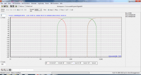
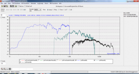
Here is a 3 way linear phase digital XO with steep slopes:

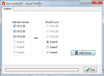
Adding the time domains together:

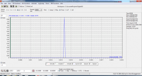
Yields:

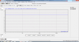
Perfect Dirac pulse. Amplitude?

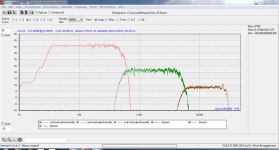
Perfectly flat. Next step is to linearize and time align the drivers. I am going to leave out the time alignment, but here are the 3 drivers raw responses:

And linearized:

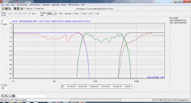
As been said a number of times, you linearize the driver within its operational range and then you convolve the drivers linearization into the digital XO which is within the bounds of the driver linearization. So when you sum the digital XO's they sum perfectly in the time and amplitude domain, just as demonstrated above, except they now contain the driver linearization:

One can see the original XO's and then the convolved XO's with both the driver time alignment and linearization.
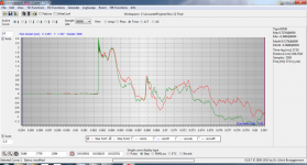
Finally, the measured step response of the 3 way steep digital XO system at the listening position:

Notice no preringing. Also note this not for one position. I took 14 measures around a 6' x 2' grid area at the LP that represents my couch and the time alignment is prefect at each spot with a very small variation in frequency response.
These images are pulled from an article I wrote in 2013, Advanced Acourate Digital XO Time Alignment Driver Linearization Walkthrough.
Since then I have done this on dozens of systems, each with progressively better results. This is the frequency and timing response of my current system using the same techniques Official Rythmik Audio Subwoofer thread - Page 1223 - AVS Forum | Home Theater Discussions And Reviews
Having read some of the comments, I am not sure I understand what the concern is?
Here is a 3 way linear phase digital XO with steep slopes:
Adding the time domains together:
Yields:
Perfect Dirac pulse. Amplitude?
Perfectly flat. Next step is to linearize and time align the drivers. I am going to leave out the time alignment, but here are the 3 drivers raw responses:
And linearized:
As been said a number of times, you linearize the driver within its operational range and then you convolve the drivers linearization into the digital XO which is within the bounds of the driver linearization. So when you sum the digital XO's they sum perfectly in the time and amplitude domain, just as demonstrated above, except they now contain the driver linearization:
One can see the original XO's and then the convolved XO's with both the driver time alignment and linearization.
Finally, the measured step response of the 3 way steep digital XO system at the listening position:
Notice no preringing. Also note this not for one position. I took 14 measures around a 6' x 2' grid area at the LP that represents my couch and the time alignment is prefect at each spot with a very small variation in frequency response.
These images are pulled from an article I wrote in 2013, Advanced Acourate Digital XO Time Alignment Driver Linearization Walkthrough.
Since then I have done this on dozens of systems, each with progressively better results. This is the frequency and timing response of my current system using the same techniques Official Rythmik Audio Subwoofer thread - Page 1223 - AVS Forum | Home Theater Discussions And Reviews
Having read some of the comments, I am not sure I understand what the concern is?
Attachments
-
 3 way NT linear phase digital XO.png194.3 KB · Views: 313
 -
 Add XOs.png65.5 KB · Views: 326
 -
 Dirac pulse.png225.8 KB · Views: 306
 -
 Summed amplitude response.png162.5 KB · Views: 300
 -
 3 way raw driver responses.png198.5 KB · Views: 313
 -
 linearized 3 drivers.png190.4 KB · Views: 316
 -
 orginal XO and convolved XO with linearization.png187.1 KB · Views: 330
 -
 timing step response no preringing.png306.3 KB · Views: 338
My point is that the pre-ringing will affect the whole response regardless of angle as it is inherent to the impulse response of the crossover filter.
This is the problem...
Neither pre-ringing or post-ringing will be audible where the crossover is behaving in a complementary manner - that is at the ideal listening point. The pre- and post- responses of the crossover sections will sum to give an overall all-pass response (that for the linear phase case will be a pure delay).
It is therefore fundamentally different to applying a linear phase for an EQ effect where the pre- (and post-) responses will be left in the filtered output because there is no complementary filter to cancel them out.
The issue with linear phase crossovers therefore is restricted entirely to considerations of the audible consequences of the off-axis residue where the complementary action no longer works.
Hence rules of thumb for linear phase EQ and listening to pre-responses from inline simulations is of limited relevance to crossovers.
Interesting I see your point now. If that holds true over over a large enough area it would make complementary linear phase crossovers very close to ideal if the latency was low enough for the application.
If that holds true over over a large enough area it would make complementary linear phase crossovers very close to ideal if the latency was low enough for the application.
In many applications, it is ideal. But there are instances where it is not so and where audible consequences can arise that are made worse because of the exposed pre-response artefacts and because of their prolongation in (negative) time.
Group delay, so long as it is not excessive, is not audible. LR4 has never been a problem. By the 8th order I am not so sure - maybe that starts to become detrimental. I do not know anything on the FIR side to comment.
I hope I am reading what the experts are saying correctly if not please correct me: the badness of steep crossovers come from this: the dispersion pattern of the tweeter changes abruptly from the dispersion pattern of the midrange or woofer, and a steep crossover slope accentuates this rift and the result sounds unnatural. If this interpretation is correct, carefully thought out horn-loading which smoothly integrate the dispersion of the drivers involved will let you use crossover slopes as steep as you want. But if this is indeed done, then there is no requirement to use steep slopes to begin with. Most of the time there is a spatial problem and an attempt is made to solve it electrically, which won't succeed.
I hope I am reading what the experts are saying correctly if not please correct me: the badness of steep crossovers come from this: the dispersion pattern of the tweeter changes abruptly from the dispersion pattern of the midrange or woofer, and a steep crossover slope accentuates this rift and the result sounds unnatural. If this interpretation is correct, carefully thought out horn-loading which smoothly integrate the dispersion of the drivers involved will let you use crossover slopes as steep as you want. But if this is indeed done, then there is no requirement to use steep slopes to begin with. Most of the time there is a spatial problem and an attempt is made to solve it electrically, which won't succeed.
Group delay, so long as it is not excessive, is not audible. LR4 has never been a problem. By the 8th order I am not so sure - maybe that starts to become detrimental.
That is true where measures are made at the ideal listening point and where steady-state signals are employed. The case for transient information may not be quite so straightforward.
I do not know anything on the FIR side to comment.
FIR filtering permits linear phase crossovers that introduce the potential for errors in a pre-response, that exceed the thresholds for audibility established (?) for minimum phase crossovers.
the badness of steep crossovers come from this: the dispersion pattern of the tweeter changes abruptly from the dispersion pattern of the midrange or woofer
That is a problem in most conventional two-way loudspeakers.
... and a steep crossover slope accentuates this rift
This is true but I do not know to what extent or have any objective experiments to help, but it is also not the gist of what is being discussed here - at least latterly. The discussion concerns the 'logic' that steep crossovers should make crossovers better, but the length of filters required for such accentuates the chance of errors off-axis presenting an audible consequence.
Most of the time there is a spatial problem and an attempt is made to solve it electrically, which won't succeed.
This is completely correct! The power of digital filtering is never a cure for not getting the basics optimised in the first place 🙂
Here is a thread on stereonet Australia that has gone through some similar information, couple of interesting points and an example of a steep passive crossover using minimal parts.
Brick wall xover filters - Speakers & Subwoofers - StereoNET
If there is a good directivity match between the drivers then a good case could be made for using a steep crossover. That is the basis for Horbach Keele crossovers to ensure that the symmetrical pairs don't interact outside their intended bands.
The Neville Thiel style of progressively steepening filters seem to offer a interesting mix of blending the drivers before shutting off the out of band stuff demonstrated in Mitchba's measurements above.
Linkwitz himself (RIP) never used a higher order than LR4 in his designs and that didn't change when he switched to using DSP. Maybe it was familiarity or because it was the best compromise.
- Home
- Loudspeakers
- Multi-Way
- Steep Crossovers...3 steps forward, 2 steps back?