@kstr
I think one of the best functions to maximize S/N ratio is log sine sweep.
I had no idea that 0.1 dB in amplitude could induce an apparent phase shift of 10°!
The more you know...
One more reason to try and come up with a direct way to measure phase?
There has to be a better way.
KS-digital used to make studio monitors with cone position control. This has no direct relevance here, but only to say that it is possible to track cone displacement in time, and from that com up with the mathematical formula of the pressure wave (at least for low frequencies, where the cone exhibits pistonic motion).
Aehm, just to avoid confusion, a Fourier transform is not the same thing as a log sine sweep. The sweep is often used as a test signal. The Fourier transform is a mathematical method to transform the test signal data from the time domain to the frequency domain.
Yes, I was referring to the signal, for S/N maximization, when I said log sine sweep.
I am aware of the difference between time domain function and Fourier transform of the function. My background is in electronics engineering.
But it's good to clarify for other people with non mathematical background. Thank you.
Or you could just forget about the speaker idea an do what Earthworks does (as described in the article). They use a "perfect" acoustic Dirac impulse. This has a very well known Fourier spectrum (constant magnitude and no phase change throughout the entire spectrum). But it's not easy to produce a sufficiently "perfect" impulse.
They recently discovered a possibly inhabitable planet a few light years away from us. Not much has changed with respect to the physics of microphone calibration, though. But I believe the article has more than you realised; it explains how they solve the chicken-and-egg problem in the calibration of their microphones by using an acoustic Dirac impulse produced by that spark thingy. This yields both magnitude and phase response.
Yes, the Dirac delta is a beautiful mathematical concept. I wonder how really close they managed to get to it, though.
Also, the impulse response test is one of the worst as far a S/N ratio.
SPL means 'sound pressure level' which IS pressure response, no difference. And it varies with incident angle.
By 'mic pressure response' I was trying to refer to the pressure-field response of the microphone as opposed to its free-field response or its diffuse-field response. All 3 are differ SPL responses due to the type of sound field the mic is exposed to. The Pressure-field response drops a little faster than a mic 90° calibration curve at the high frequencies. Since I don't have direct access to the pressure-field response of my mic I use the 90° calibration curve as a reasonable approximation of it. It should thus result in a slight underestimation the actual phase rotation.
The phase thing is interesting though, do you have a reference for that?.
I found this:
https://www.bksv.com/media/doc/be1447.pdf
It appears to be an updated version of the old document I remember. A quick scan did not reveal a clear statement that the mic pressure-field response is the best curve to use to estimate the phase response. As I indicated, I am not sure exactly where my source for that thought came from. It seems logical to me that the pressure-field response would be the controlling mic characteristic so possibly I just inferred it from the language here, or in the older version. It could also have come from another source. In any case, it is logical to me that the mic is either minimum phase, or that also contains some excess phase. If it also contains excess phase then I would expect the phase rotation to even greater. This is just my hobbyist take on the matter.
My overall thinking is that using the 90° calibration curve underestimates the true phase value and thus is a better estimate than assuming there is flat linear phase response of the mic.
I've learned that mics are min-phase and the rising and ripply response at HF is the exact same phenomenon than a speaker's baffle step, which is minimum phase.
How could the *same* pressure response pattern at the same time be non-minimum phase for a microphone and minphase for a speaker? EDIT: I see jcx asking the same question....
I wouldn't expect the pressure-field response of the mic to have a significant diffraction issue being representative of a mic measured flush to a plane surface. I also expect that most all of the ripple in the 90° cal curve of my mic is due to variability in measuring system used. The mic itself may have a minor resonance or two, but it is impossible for me to separate them from the measurement variability. I thus smooth out all those minor ripples, as shown in the chart I posted, so that their impact is not present in the SPL or phase response.
See attached plot from a Schoeps document, Joerg Wuttke's "Microphone Essays" (the most reputable source you might find on microphones), showing reponse rise of a point receicer at the center of a disc, exactly how typical electret capsule construction look like. EDIT: it's not a disc, it's a square, but response pattern aren't too different.
I'm not sure how the response of a diaphragm helps. I am looking to compensate for the overall response of the microphone including the entire microphone assembly and mic preamp. The dozens of the SPL charts I have see all basically do not have that degree of SPL ripple.
Remember, I am only sharing my current thinking for discussion and the learning opportunity. I certainly am not an expert on microphone characteristics.
I am not aware of any practical impact of going to this trouble of including phase in in mic calibration. [I originally did this work to determine how much impact there would be to the REW step response when the measurement system loopback calibration and microphone calibration IR's were included. The REW step response does not include those elements.]
I am not aware of any practical impact of going to this trouble of including phase in in mic calibration.
There is a lot of software out there that claims to have enough DSP design capability to linearize phase, as well as amplitude.
People seem to buy these products, and I intend to do the same for my single driver speaker project.
However, without knowing for sure the phase response of the calibration microphone, one can only aspire to make the speaker behave like the microphone, for better or worse, as far as phase response.
Yes, to clarify:
My hobby is optimizing the setup per measurements so I still employ the mic phase impact in my overall correction and achieve reasonably linear phase of the direct sound 20-20k Hz.
The microphone phase impact to the overall phase rotation in my setup is very small however. With my subnormal hearing ability, I am not able to detect any difference in sound quality when removing all the overall phase rotation in my system including the mic. Thus, for me it improves the accuracy of measurements, but has no practical sound quality value.
Improving the measurement results in other ways has lead to very obvious improvements/differences. XO choices and the phase relationships between drivers within a channel is very important and easily detected at least for the lower frequency XO's.
The phase tracking relationship between drivers is not impacted whether the mic phase is included or not. That is a relative phase issue. The mic phase only impacts the overall phase rotation, not the relative phase between drivers.
It's only the impact of the overall rotation that seems to escape me. Others report different experiences and it is impossible to me to comment on what others are able to hear. I just conclude that for me is that the phase relationship between drivers is important while at the same time I don't seem sensitive to the the overall phase rotation.
I am talking about relative phase too.
One needs to know the phase response of a microphone to correct the relative phase shifts of a speaker measured with that microphone.
One needs to know the phase response of a microphone to correct the relative phase shifts of a speaker measured with that microphone.
Yes, if I understand your comment correctly; "relative phase shifts of a speaker measured with that microphone" to me is referring to a single measurement intended to obtain the true/accurate phase of that speaker. That could be a multiway speaker, or a single driver. To get that true/accurate phase we do indeed need the mic phase information. We would have a small error if the mic phase was not included in the calibration.
By 'relative phase' I am referring to identifying the phase difference between 2 different measurements. If we don't have, or just don't use, the mic phase response in our calibration, we can still find the correct 'relative phase' between 2 different measurements. For instance; we can find the needed delay timing to use in a DSP speaker management box such that the IIR XO handoff between a midwoofer and a tweeter provides close phase tracking of the 2 drivers throughout the XO range. The same correct delay timing will be found whether the mic phase is used, or not used. This is what I meant by the relative phase between 2 drivers.
I find that changes in the relative phase between drivers creates noticeable sound differences. I find differences in the true/accurate overall phase rotation is not detectable by me.
After carefully aligning the phase relationship between drivers by setting proper delays in IIR XO's, I end up with roughly 840° of overall phase rotation of each channel consisting of SW's, midwoofer and tweeter when using the mic phase information. If the mic phase is not used the total rotation measured is maybe 800° for example. I hear no difference whether I then remove some, or all, the that 840° phase rotation and thus approach linear phase for the overall system.
My experience is that the driver to driver phase tracking through the XOs is the most important issue. I suspect it is not important whether one uses IIR XO filters set for close phase tracking and then lastly remove the overall phase rotation with a rePhase FIR filter as I do, or if one uses the popular method of first setting linear phase of each driver independently and then using linear phase XO filters. In either case, we end with linear phase overall and linear phase of each driver including within the XO range handoff.
A few short notes. More later. Measurement microphones like B&K are calibrated for response with an electrostatic calibrator that uses the diaphragm as the speaker. This removes any intermediate air etc. from the result and has zero time delay. This doesnt work for ecm mikes it seems. The output is the pressure response and needs to be corrected to be the free field response showing the effect of the diaphragm and housing in free space. The free field mikes are "tuned" to correct for the rolloff. The correction curves are in the B&K lit. They are the same for microphones with the same diameter.
Even the spark impulse is not ideal since its actually a shock wave with finite rise time.
Most microphones do have a lf limit or they would pop in air transport etc. Usually closer to 10 Hz. Its done with a small port to the back side of the capsule.
I have a 4133 and a 4135.and a 4136. I need to do some calibration checking since I'll need to check for "HiRes" performance of some speakers/headphones. Ill share what I learn. There is a whole lot to this making it very difficult. When the wavelengths get short (40kHz) a millimeter will change the responotce to a speaker and the air field is far from uniform.
To further mes this up is nonuniform loss through air. I don't know if the delay is constant with frequency in air but I doubt it if the amplitude response is not.
Sent from my LG-H811 using Tapatalk
To further mes this up is nonuniform loss through air. I don't know if the delay is constant with frequency in air but I doubt it if the amplitude response is not.
The delay relates to the speed of sound in the air which is constant, while the amplitude relates, probably more than anything else, to the dispersion characteristics of the source. So at least on this point I think we can be safe.
I just had the opportunity to ask these questions to one of the principles of GRAS.
1) Phase response on the measurement microphones is direct measurement from the electrostatic actuator. No intervening corrections etc.
2) The electrostatic actuator can be used to 400 KHz although the microphone won't have output. its a pressure response curve and needs to be corrected to free field if used that way. He also confirmed that a pressure response mike + correction curve can be used as a free field mike if your software supports it. You can create the correction from B&K's published plots with at worst a +/- error of about 1 dB.
This leaves a challenge that's really interesting- fabricate an electrostatic actuator for an ECM microphone. On paper is should work if the diaphragm is conductive. Does anyone know?
I just had the opportunity to ask these questions to one of the principles of GRAS.
1) Phase response on the measurement microphones is direct measurement from the electrostatic actuator. No intervening corrections etc.
2) The electrostatic actuator can be used to 400 KHz although the microphone won't have output. its a pressure response curve and needs to be corrected to free field if used that way. He also confirmed that a pressure response mike + correction curve can be used as a free field mike if your software supports it. You can create the correction from B&K's published plots with at worst a +/- error of about 1 dB.
This leaves a challenge that's really interesting- fabricate an electrostatic actuator for an ECM microphone. On paper is should work if the diaphragm is conductive. Does anyone know?
I posted a teardown of a typical ECM on the micbuilders Yahoo site along with dimensional measurements. IIRC the diaphragm appeared to be metalized but I don't see how one could arrange an actuator without modifying the acoustic "circuit" and hence obscuring the true phase response or destroying the mike.
@Demian your PM is full.
Last edited:
PM fixed. Can you post a link to your teardown? Electrostatic actuator for an ECM is probably a pipe dream but lets look closely. I have the 1/4 B&K's but above 20 KHz there are so many issue that can compromise a measurement transferring a calibration seems unlikely to be very successful.
PM fixed. Can you post a link to your teardown? Electrostatic actuator for an ECM is probably a pipe dream but lets look closely. I have the 1/4 B&K's but above 20 KHz there are so many issue that can compromise a measurement transferring a calibration seems unlikely to be very successful.
I'll dig it up if I can, and glad to help if possible.
EDIT - Yahoo groups no longer recognizes my email and I can't be bothered to deal with it.
Last edited:
I have come to detest Yahoo groups. They broke it with a revision only a teenager could appreciate a few years ago. I'll try to search for it.
No luck and too many distractions trying to search for the ECM info. What part of the acoustic path becomes an issue for the electrostatic actuator?
No luck and too many distractions trying to search for the ECM info. What part of the acoustic path becomes an issue for the electrostatic actuator?
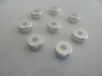
Here's a pic of some Primo capsules. If you realize the diaphragm is behind the array of holes and the entire assembly is permanently sealed by rolling the edge over a small round PC board on the back the problem becomes apparent. The array of holes is crucial in tuning the response of the cavity between the front and the diaphragm inside. I ground off the back of a similar one, there is a backplate with the gate of a FET butt welded to it the drain and source come out the back into the PC board, a plastic spacer ring, and then a metal ring supporting the diaphragm. I measured the thickness of the spacer and the diameter of the exposed diaphragm and it computed exactly 10pF from the capacitance equation. Inside there is a round plastic former that holds everything in place which is pressed into the outside housing to tightly control all the critical spacings. IMO opening or removing the front to place an actuator would totally change the high frequency response.
EDIT - I assumed in my case the diaphragm was simply a metalized plastic and the backplate had a teflon coating that carried the built-in polarization charge.
EDIT - IIRC there are numerous mod articles around that enlarge/modify the front of ECM's to change their frequency characteristics.
Attachments
Last edited:
That explains a lot. The Primo capsules are very good. I was thinking of the Panasonic capsules WM-7? (discontinued) which I believe have an exposed diaphragm. Gras also said for measurements above 40 KHz you need to remove the grid. That's always risky but may explain why I was have such trouble getting good measurements above 40 KHz on a Panasonic ribbon tweeter. I need to try again.
Is the metal grid on the Primo connected to ground in a way it can be disconnected easily?
Is the metal grid on the Primo connected to ground in a way it can be disconnected easily?
That explains a lot. The Primo capsules are very good. I was thinking of the Panasonic capsules WM-7? (discontinued) which I believe have an exposed diaphragm. Gras also said for measurements above 40 KHz you need to remove the grid. That's always risky but may explain why I was have such trouble getting good measurements above 40 KHz on a Panasonic ribbon tweeter. I need to try again.
Is the metal grid on the Primo connected to ground in a way it can be disconnected easily?
The Linkwitz mod frees the housing so you can make a source follower out of it, unfortunately I think the diaphragm and case are electrically connected by the metal ring that acts as a spacer for the front cavity. You can OTOH now use the diaphragm as an input coupling cap if you can think of anything this is useful for.
The Panasonic WM series has one small port in the front, I assume that changing the diffraction around or near this port would affect the phase enough to make a good cal impossible.
The holes are acoustic resistances so some claim removing the front and equalizing the mic flat again can remove a few dB of noise.
EDIT - You could try a needle as a point source of charge right at the port input, probably would need a lot of volts AC on it.
Last edited:
- Status
- Not open for further replies.
- Home
- Design & Build
- Equipment & Tools
- State of the art of measurement microphones phase response calibration