gtforme00 said:You mean, besides the 12000uF 50V Snap-in caps from Apex Jr. that are already on the BOM?
You must have missed them. 😀
-David
Sorry man! I think I did miss them. That's the big slow Nichicon? I like those. You can get a little more "slam" to the bass by using some good power caps (from 1500uF to 3300uF) directly at the rectifier. These guys are young, after all. 😉
Proposal: Some 2200uF 63v Nichicons getting "hit" by the rectifier noise, and then the now-improved output from that, going into your 12,000uF tanks. The big caps will work better if they're protected from the rectifier output.
Thinking about the transformer options, and it looks like that 2.7 amper model can support either 4 ohm or 8 ohm speakers. When using a dual rectifier, the voltage lowers slightly, while the rectifier becomes twice as strong.
That can all work together to help reduce system heat as well--clean power makes for cooler chipamps. And that can work with the cute little enclosures. 😉
Have fun guys!
Just barely, I have a to-scale drawing on my desk and I can lay out one of the apexjr toroids plus one chipamp.com power pcb and two chipamp.com amplifier pcbs comfortably. I don't know how much noise would be picked up due to the proximity of the amps to the xformer. Some type of internal divider might be necessary to shield the boards.
Internal dimensions are:
D W H
Inches 8.66 6.122 1.853
mm 220 155.5 47.06
It is Hammond Part #1455T2201 or #1455T2201BK (Black)
Datasheet
There are some similar designs on ebay, I've contacted some of the sellers for volume pricing.
The Hammond is rather pricey at around $30 for single piece quantities. The advantage of the Hammond case (besides being cute) is that it is available from Mouser, who I am currently rebuilding the BOM through. The shipping on that other case (still handsome in my opinion) was high for single piece orders, making the cost about the same as the Hammond if one were to order it individually (~$30). I do have some concern about the ventilation in the Hammond case, but we can't know if it will be an issue till we try it.
The last thing I need is another project, but it would be hard not to build one if I'm going to do all this work to plan it out. Plus, someone has to test it first right? 😀
-David
I think 12000 uF of supply capacitance might be overkill for the 2.7A rating of the highest current transformer. With the PSRR of these chips, we could probably get away with 4700 uF per rail for the smaller transformer. The 2.7A guy would probably need closer to 6800 uF or 8600 uF minimum.
It really depends on whether the surplus one's at apexjr are short enough to fit in the case when mounted to a PCB. Anything even slightly over 40mm tall will not fit when mounted on a board. If they fit, then no harm done, they are less expensive than most other capacitors half their value. If they do not fit, I do not think I will look for a 12000uF replacement, but instead find the largest value that both fits and is economical.
-David
gtforme00 said:I think 12000 uF of supply capacitance might be overkill for the 2.7A rating of the highest current transformer. With the PSRR of these chips, we could probably get away with 4700 uF per rail for the smaller transformer. The 2.7A guy would probably need closer to 6800 uF or 8600 uF minimum.
It really depends on whether the surplus one's at apexjr are short enough to fit in the case when mounted to a PCB. Anything even slightly over 40mm tall will not fit when mounted on a board. If they fit, then no harm done, they are less expensive than most other capacitors half their value. If they do not fit, I do not think I will look for a 12000uF replacement, but instead find the largest value that both fits and is economical.
-David
For that transformer, its 6600uF per rail although you could use more if you wanted. Its also two rectifiers.
Least expensive this way:
6 of
http://cgi.ebay.com/ws/eBayISAPI.dll?ViewItem&item=150195500216
2 of
http://cgi.ebay.com/ws/eBayISAPI.dll?ViewItem&item=150185069831
Detail:
Since the 4 amp rectifiers are in series, it makes one 8 amp rectifier. Since the 35v caps are in series, it makes a 70v peak capacity of which that transformer will not exceed. That store does shipping combos, which reduces the price of volume orders. The size of this power supply, whether used as 6600uF or 8800uF, will be very short and small in size. Note: Bleeder resistors are highly recommended for student project power supplies. EDIT: Check the price vs performance, and I think its good.
Attachments
6 of those in series pairs is only 3300uF.danielwritesbac said:
For that transformer, its 6600uF per rail although you could use more if you wanted. Its also two rectifiers.
Least expensive this way:
6 of
http://cgi.ebay.com/ws/eBayISAPI.dll?ViewItem&item=150195500216
I have plenty of capacitors to experiment with for now, thank you for the offers and suggestions; I'll keep them in mind.
I guess I'll just have to build up an amp and see what happens.
Here's the plan: I'm going to order what is on my BOM. I have some www.chipamp.com boards left over from a project so I'm going to use them to build the whole deal up. I'll make sure it all works and is easy enough to construct without problems.
From there, we'll gauge interest and see if this is going to be bigger than just locally.
-David
been a busy night for me, first week of classes.
We got tentative approval to proceed. The only stipulation is that we need to make sure we don't use leaded solder.
I'm going to build a prototype out of my personal funds to give us somethign solid to present, along with our 'lesson plan' to get final approval for the project.
As of now, we are thinking about a total of about 20 of these being built. We may take a head count of those interested and adjust based on that.
Unless I listed the wrong cap, 3x2200=6600. Three parallel caps per each rail. Calculations of voltage handling is from V+ to V- "as if" the caps are in series, which is how the tolerances are calculated in commercial power supplies. For example: The 43vac gets split in two, now two rails of 21.5v each, increased by 1.4 by the rectifier, thus exposing each cap to 30v.error401 said:6 of those in series pairs is only 3300uF.
theAnonymous1 said:I have 2200uF 50v Nichicons and 820uF 63v Panasonic FC that I can give a good deal on.
The 2200uF 50v caps would be safer than the 2200uF 35v caps and higher voltage tolerance allows a wider choice of transformer.
However, the approximately 34mm to 38mm tall 50v caps do take more clearance than the 31mm tall 35v caps.
Suggestion, get a larger case and use the more-durable 50v caps.
Caps in series divide. Two 2200uF caps in series gets you one 1100uF cap with double the working voltage. Put three of those in parallel and you get 3300uF.
error401 said:Caps in series divide. Two 2200uF caps in series gets you one 1100uF cap with double the working voltage. Put three of those in parallel and you get 3300uF.
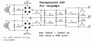
Yes, and no. The 0v line is connecting at the centrepoint of the series caps, as is seen in the majority of power supplies, including this one:
EDIT: You do have an excellent point in that the chipamp sees only the difference between V+ and V-, therefore the typical power supplies may have greater working voltage tolerances and less capacitance than we would assume--like the Carlos FM supply below would max at 100v, but is actual 6,650uF. Even so, it seems sufficient.
Attachments
Ah, I was thinking you were talking about per rail capacitance, as you normally see it discussed. I guess if I thought it through I'd have realized the voltage concern wouldn't have made sense then. Sorry for the confusion.
error401 said:Ah, I was thinking you were talking about per rail capacitance, as you normally see it discussed. I guess if I thought it through I'd have realized the voltage concern wouldn't have made sense then. Sorry for the confusion.
I thought you were talking about a comparison of single rails versus dual rails. In that context, it made good sense.
EDIT: I was trying to illustrate how the tolerances are calculated on commercial amplifiers to have them as small as possible--because of the very small amplifier enclosure.
And, we did cover it!! 😉
EDIT2: This was a good example of how the tolerances of parts can be compromised due to lack of 3mm of extra space in the enclosure. I'd rather go with better parts and the needed space to fit them.
Thanks again!!
no, it doesn't.danielwritesbac said:
Detail:
Since the 4 amp rectifiers are in series, it makes one 8 amp rectifier.
Your arithmetic/advice stinks.
don't apologise.error401 said:Sorry for the confusion.
It's Daniel's use of very non standard electrical language that causes most of the confusion.
AndrewT said:
no, it doesn't.
Your arithmetic/advice stinks.
Pardon me sir, but I'd like for you to look that one up.
Like this:
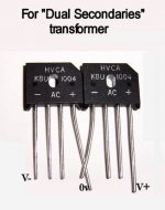
1 of 8 amper rectifier with a center transfomer
vs
2 of 4 amper rectifiers with a dual secondaries transformer.
It wasn't my opinion, but rather reference materials; however, I would like to know if a dual bridge is not actually twice as strong as a single bridge, and I would like to know, if not the 2x commonly referenced, then what figure is approximately comparable in practice? Thanks!
what was that about confusion due to non standard language?danielwritesbac said:if a dual bridge is not actually twice as strong as a single bridge
AndrewT said:what was that about confusion due to non standard language?
That was in reference to a 1 piece bridge rectifier unit, like these examples:
Attachments

- Status
- Not open for further replies.
- Home
- Amplifiers
- Chip Amps
- Starting a student project, need some input (chip amp + speaker set)