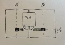
Mounting should be approx at 1/3 from bottom for most effective heat transport.
There is a marking line scratched already.
Use thermal paste as little as possible: it only has to fill in the (near atom size) gaps of the metal, or use silpads.
If applied as peanut butter, it forms a heat isolator instead.
When you search on the internet how to apply heat paste, the results are tasty!
This is the best picture after a quick scan:
https://www.gamingscan.com/wp-content/uploads/2018/12/how-to-apply-thermal-paste.jpg

If I observe the pictures right, your thermal resistance between the transistor case and the heat sink is much too large. This may explain why your transistor case temperature is too high. Follow the advices from Citizen in the former post. It is not anything wrong with th transistor couple 2SC5200+2SA1943; I have used these excellent transistors for years without any issues.
knutn: You mean the ceramic isolators is to big or to thick? I have not taken temp on the 2s transistors ( I think ). But heatsink got 55 degrees ( with Hiraga 30w without Kubota ). Kubota version got only 35-37 degrees.
Frank
Frank
Yes, but use heat shrink tube to isolate the legs also.
Shrink tube is teflon, and perfect to withstand the heat.
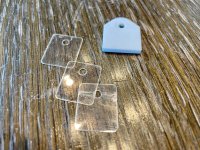
The mica's are ok, use very little thermal paste: the less the better, both sides.
I cannot imagine where the ceramic slab is used for. A tombstane for dead semi's?
Shrink tube is teflon, and perfect to withstand the heat.
The mica's are ok, use very little thermal paste: the less the better, both sides.
I cannot imagine where the ceramic slab is used for. A tombstane for dead semi's?
Ok, I have some silver plated copper cable with teflon from Habia ( 1.2 mm2 ).
Or I can use copper singelcore with teflontube, have that also.
The silpads, are that the "best" to use?
Frank
Or I can use copper singelcore with teflontube, have that also.
The silpads, are that the "best" to use?
Frank
Teflon heat shrinking tube over (tinned) copper wire. Bend first, then shrink.
Silpads does not annoy like the (breaking) mica's and polluting paste.
Even better thermal specs. Preferable.
Silpads does not annoy like the (breaking) mica's and polluting paste.
Even better thermal specs. Preferable.
https://en.wikipedia.org/wiki/File:Thermal_conductivity.svg
Ceramic will be near glass and concrete.
AFC: "...I did find something better"
Well?
Ceramic will be near glass and concrete.
AFC: "...I did find something better"
Well?
Why, compared on specifications?ON Semiconductor MJ15024G+MJ15025G. 🙄
Citizen124032: Must I use heatshrink, or can I use teflontube? I look at silpads.
AFC: Can you please stop laughing at my transistors and just give us your holy grail, damn!! ( :
I have that 10cm and .75m2 in mine.
AFC: Can you please stop laughing at my transistors and just give us your holy grail, damn!! ( :
I have that 10cm and .75m2 in mine.
I would use 1mmq tinned copper wire and suitable heat shrink tubing. That is also made of teflon, but it shrinks and I do not know if your teflon tube shrinks. I like it better that way. 1mmq can handle 10A (domestic safety rules), 16 for industrial. 0.75mmq is 6A domestic and 10A industrial.
But in general, as mentioned by AFC, the longer the wires, tho larger the antenna (transmitting and receiving.
Can you not just shove the pcb as is upwards? Point is the have the semi's at the right place (@ 1/3H), the pcb is of a minor issue.
Or with the semi's @ 1/2H, have the pcb's downwards, also a good option.
I'd prefer to consider the length of the legs of the semi's as a max stretch.
Curious enough, I've a Hiraga 8W at my home, bought on a (somesort of local) ebay site, with 12cm twisted flex wires 1.5mmq CBE together, ment for domestic installation wiring (brown-blue-yellow) actually, and does not oscillate or other nasty things (like unwanted radio reception). Still a miracle, yet a marvalous sound.
AFC: "Only subjective feelings."
Hmmm... With respect, and without going into laborous discussions about relevance of subjectivity, what are those feelings? Opinion is a viewpoint, and does not have to represent the strict middle of the road. Or we all were nowhere.
Hmmm... With respect, and without going into laborous discussions about relevance of subjectivity, what are those feelings? Opinion is a viewpoint, and does not have to represent the strict middle of the road. Or we all were nowhere.
Good morning, I go for the no cable mount. Rise the pcb 50mm, then im spot on at the 1/3 H.
The 8w sound so good, I listen to that every time I visit a friend.
Just to get it correct, does have teflon shrink on the legs of the transistor help the transistor stay cooler or is it just for isolation ( safety )?
Frank
The 8w sound so good, I listen to that every time I visit a friend.
Just to get it correct, does have teflon shrink on the legs of the transistor help the transistor stay cooler or is it just for isolation ( safety )?
Frank
AFT: Thanks, they are contacted against same bottom and top plate. But I can take them to work and tig weld them together.
But maybe its ok as is?
Frank
But maybe its ok as is?
Frank
Citizen124032: No, weld the two heatsink together. But thats maybe not importent, may just leave it as is.
Frank
Frank
Pfiew!
When not weld together, the thermal separation is better. Unknown of this improves electronic stability.
Knowing that the MJE-drivers must be separated from the output semi's, my intuition says have them all separated.
If one component is thermally deviating, the local feedback (Sziklai) and overall feedback can act more 'direct'.
There is little to none documentation available about this on the Hiraga's.
- Home
- Amplifiers
- Solid State
- Start up Hiraga 30W w/Kobuta reg