It was just a test setup.. but since you're so damn clever I'll leave you to it"I think the regs only adjust dc on output."
If you mean the DC voltage regulator circuit's, they're for the supply voltage of +/-22Vdc only, not for the DC-offset on the output of the amplifier.
Make sure these regulators provide a symmetrical +/-22Vdc supply for the amp.
"I think R9 R10 are the ones."
About what?
"It is this one?"
Which one (-'s)?
"As I remember I found the correct value by inserting trimmers, adjusted to correct, took trimmers out and substituted them with resistor."
You mentioned this, but are these resistors of the same value? In the circuit 1k5//3k0 are shown.
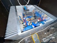
Q5/Q6 are on the little 'bend-fingers' heat sinks (separate from each other, I hope) on the pcb, so that's ok.
The heatsinks for Q7/Q8 are not 'huge'. They're small actually.
Oh no, you've used utp-cable wires as hookup wires... they're not made for this purpose (they break).
Better replace them with decent wires.
Using the regulated supply to adjust the output offset?...and corrects the offset, its nor that confusing
Where do you use P1 for then?
And after adjusting the output offset with the regulators, you adjust R5/R6 to get the right idle current...
After some fourty years in electronics, this sounds pretty weird to me.
Citizen124032: I only change led from red to white. same spec. The R9 / R10 is as what comes with the kit.
The regulated supply ( Kubota ) is for the input step. P2 / P3 is for adjust the +-22Vdc. P1 for DC offset.
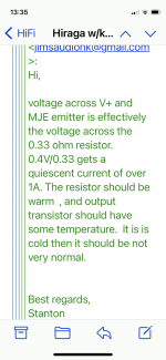
amplidude: I see you have the Kubota version, What do you messure over the 0.33Ohms?
I think I go back for the 30W without Kubota. It plays in class A that it suppose to do.
Frank
The regulated supply ( Kubota ) is for the input step. P2 / P3 is for adjust the +-22Vdc. P1 for DC offset.
amplidude: I see you have the Kubota version, What do you messure over the 0.33Ohms?
I think I go back for the 30W without Kubota. It plays in class A that it suppose to do.
Frank
Hi, nothing realy. Sound good, dont get warm. All good ( : Its just that it bother me a tiny bit, sold as Hiraga 30W class A with Kubota regulation.
But, it dosent run much in class A. Dont run warm ( as real class A does, high bias ), dont consume any wattage at idle ( 29W compare to 300+W ).
I want my class A back !! As we know, thats the ting ( ;
Frank
But, it dosent run much in class A. Dont run warm ( as real class A does, high bias ), dont consume any wattage at idle ( 29W compare to 300+W ).
I want my class A back !! As we know, thats the ting ( ;
Frank
I'm blind. White appears as green. Proven science is in doubt, dodo-media rules....change led from red to white. same spec...
Thanks for the support sofar AFC, and way beyond the contemporaries of our times.
I built several Class A and Le Monstre also. You do not need to afraid from these circuit/amplifier. Not that difficult to set up the bias.Hi, nothing realy. Sound good, dont get warm. All good ( : Its just that it bother me a tiny bit, sold as Hiraga 30W class A with Kubota regulation.
But, it dosent run much in class A. Dont run warm ( as real class A does, high bias ), dont consume any wattage at idle ( 29W compare to 300+W ).
I want my class A back !! As we know, thats the ting ( ;
Frank
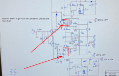
Please take a look at the red arrows. Remove those resistors (4Pc), Use each side one 1K multi-turn (15 times) trimmer pots. The middle pin of the trimmer connect it together with one of the (bend and solder it) pin and adjust it to max (1K). Solder both trimmer the same way to your PCB at the place of the Resistor R9 and R10. Turn on the amp and start each side to reduce the trimmer by half turn until you get the required Bias. It is easy. After you set up you can replace those trimmers with resistor or you can leave it like that. That is how I set up my Le Monstre and some other similar amps.
Attachments

Citizen 124032: I got 632mV across R9/R10.
gaborbela: I see what you mean, I look at that. In the document Lampie 519 show us the builder had 1.65A @ 35V give him 58W.
I got 1.2A @ 25V give me 30W. Iqs times 2 to load I got: 1.2A times 1.2A times 8 Ohm is 11.90W class A.
What am I missing here, do I have a amplifier that gives me 11.90W in class A or not?
It does not get warm, but I got big heatsinks.
Frank
Attachments
632mV over R9, 402mV over R13. Leaves 230mV over Q6be. Same with Q5be.
Where's the idle current (1.2A!) through Q7/Q8 running from? Q5/Q6 twisted legs?
This kobuta and Q9/Q10 additions go nowhere. #20, last line.
Where's the idle current (1.2A!) through Q7/Q8 running from? Q5/Q6 twisted legs?
This kobuta and Q9/Q10 additions go nowhere. #20, last line.
If Q5/Q6 have only a Vbe of (approx) 0.23V, they not conducting.
If they're not conducting, Q7/Q8 should be closed too.
If you still measure 400mV over R13/R14, it means there is a current of 1.2A running through them.
But where does that current go to if Q7/Q8 are closed?
The only other way is through Q5/Q6... so they're broken or wrongly placed.
Or something else.
Can you measure all voltages on the semi's Q1 - Q8 and Q9 & Q14?
Hi, I will messure in the morning before job. I do my best ( : bare with me Im just a mecanic.
Frank
Frank
Hi, now I have measure; only on pcb for right canal. Q1-589mV Q4-584mV Q12-587mV Q-13-582mV. I try to measure Q5 but its so tight, so I measure between base (1) and leg off R15.
Then I got 25.4V. Maybe I did it wrong, and after try one more time there comes a little smoke ring. Maybe I shorten some thing, I stopped there. All measuring without speakercables and input shorten.
Connected the amp back up, no sound in right canal. Maybe its a sign that I must put in the old cards ( :
Frank
A bias current of 1.2 A gives a peak current of 2.4 A, which has an RMS value of 2.4A/sqrt(2) = 1.7 A, so the output power with a resistive 8 ohms is 1.7 times 1.7 times 8 = 23 W.I got 1.2A @ 25V give me 30W. Iqs times 2 to load I got: 1.2A times 1.2A times 8 Ohm is 11.90W class A.
What am I missing here, do I have a amplifier that gives me 11.90W in class A or not?
It does not get warm, but I got big heatsinks.
Frank
If you want 30 W into 8 ohms, the bias current must be at least 1.4 A.
Angry Fat Cat: The Hiraga 30W pcb without Kubota.
knutn: Tanks, but why the huge difference in heat. 20 degree warmer from 23W to 30W? I dont understand.
Frank
knutn: Tanks, but why the huge difference in heat. 20 degree warmer from 23W to 30W? I dont understand.
Frank
I've the impression that you've measured the various Vbe's, but what can reveal most are the absolute values to ground.Hi, now I have measure; only on pcb for right canal. Q1-589mV Q4-584mV Q12-587mV Q-13-582mV. I try to measure Q5 but its so tight, so I measure between base (1) and leg off R15.
Then I got 25.4V. Maybe I did it wrong, and after try one more time there comes a little smoke ring. Maybe I shorten some thing, I stopped there. All measuring without speakercables and input shorten.
Connected the amp back up, no sound in right canal. Maybe its a sign that I must put in the old cards ( :
Frank
Except for Q5/Q6, which are better measured to their respective supply rails.
So all voltages for Q1, Q2, Q3, Q4, Q5, Q6, Q7, Q8 and Q9 and Q14. The output offset (dc, in mV's) and supply voltages (V's) are helpfull too.
That's the normal practice for analysing electronic circuits.
Sorry to hear you're back to mono... alas. And I pm-ed you to take time and care!
Citizen124032: I try to take time and care but I may have to little knowledge about electricity. All I do is on my own shoulders, blaming no one ( :
I check the MJEs, if Im lucky I can change and the amp is back up again.
What I think vent wrong was that I shorten leg 2 and 3 on the MJE.
Frank
I check the MJEs, if Im lucky I can change and the amp is back up again.
What I think vent wrong was that I shorten leg 2 and 3 on the MJE.
Frank
Frank, their are near 500000 members here and many to support you.
Without doubt, you have your own talents and blessings.
Now to decode your "leg 2 and 3 on the MJE": that will be Q5/Q6 but check Q7/Q8 too!!!
Without doubt, you have your own talents and blessings.
Now to decode your "leg 2 and 3 on the MJE": that will be Q5/Q6 but check Q7/Q8 too!!!
Good morning, the MJEs and the 2sc5200 / 2sa1943 is broke.
Got constant bip ( diode reading with bip, FLUKE ) and reading 3mv on one of the 2s, and the adder no reading at all.
Tested with a good 2s and that give me a singel short bip and read 513mV
Frank
Got constant bip ( diode reading with bip, FLUKE ) and reading 3mv on one of the 2s, and the adder no reading at all.
Tested with a good 2s and that give me a singel short bip and read 513mV
Frank
- Home
- Amplifiers
- Solid State
- Start up Hiraga 30W w/Kobuta reg