I am building my first vacuum tube project and need a little help with the grounding scheme.
I would like to use a star ground system, unfortunately I do not totally understand how to implement it.
I have read about local ground nodes and then running one wire to the star. Is the local node to the chassis or is it isolated?
For my star connector, I have a 1" diameter, 5/16" thick machined copper, with 24 holes drilled in it, in a circular pattern to accept my various wires. Does this get isolated from the chassis and then tied to the green ground wire from the mains?
I have nylon washers for my RCA inputs and outputs, which seem to isolate them from the chassis, so I plan on using them.
Any help with grounding of a tube project ( in this case a Grounded Grid preamp ) would be appreciated.
Thanks
Gary
Hi,
everything needs to be isolated from the chassis for this grounding scheme to work. When done there should be only two connections to the chassis. The star ground and the earth ground.
everything needs to be isolated from the chassis for this grounding scheme to work. When done there should be only two connections to the chassis. The star ground and the earth ground.
Hi Gary,
The term "star ground" I believe is somewhat of a misnomer. It comes from the way some schematics are drawn on paper, and because some builders run their wires verbatim to that style of drawn schematic. Another practical term could be "single point" ground that is also widely accepted.
The whole concept is very simple. Make all power and signal grounds connect together at only one point to the metal chassis. The green mains earth wire connects there also. That point is generally somewhere near the center of the chassis.
This can be done by extending several wires from various circuit ground points to converge at the center "star" location. That location is connected to the chassis. Your copped disc will work here but may require a lot of soldering heat due to it's thickness.
Another way (the way I prefer) is to use a ground buss wire. A ground buss is a heavy bare copper wire suspended near and around the tube sockets. All local ground points of the circuit are soldered to this nearby buss wire. The buss wire is then, in turn, connected to the metal chassis at only one point. Usually near the center as in the star methode.
Also, the best ground point for the buss can be determined experimentally by connecting it to different points on the chassis while listening with a small speaked or phones for lowest hum level with no signal.
I hope this clears things up a little.
Victor
Thank you for the reply.
Can I connect my earth ground directly to the star also, or should there be two separate connections?
Can I connect my earth ground directly to the star also, or should there be two separate connections?
HollowState said:Another way (the way I prefer) is to use a ground buss wire. A ground buss is a heavy bare copper wire suspended near and around the tube sockets. All local ground points of the circuit are soldered to this nearby buss wire. The buss wire is then, in turn, connected to the metal chassis at only one point. Usually near the center as in the star methode. [/B]
ABSOLUTELY. I have been doing things that way for years and it usually works out best. As was previously mentioned, the misconception about a 'star-ground' is that you have a spider-web of wires running from each ground node to a common ground reference point, but as long as you reference the grounds of the amplifying stages to their proper respective PSU stage ground node--even along a 'bus' -- and then reference either each node (or a single node of the bus itself if you use that method) to a single common ground reference point, then the actual 'star' connection is just an equal-and-common reference for all the stages and you have achieved a 'star-ground' (albeit one that most people confuse with a bus ground at first glance). Using this type of scheme that HollowState pointed out, will also save you quite a bit of wire and effort, while keeping the build cleaner looking and simpler at the same time.
Victor,
You are right about the copper disc. After I posted I went out to the garage to try soldering a wire to it, and I could not get the solder to flow in the hole. So, I was going to ask if I could use a buss wire, but you answered that question for me already.
I cannot believe how after reading everything I could get my hands on for a few years now on tubes and tube theory, how hard it is to actually apply it all for the first time. I have wrestled with the chassis layout, component selection, and wiring. It is definitely a learning process.
Gary
aletheian said:
will also save you quite a bit of wire and effort, while keeping the build cleaner looking and simpler at the same time.
Not only. Long multiple wires to ground suffer more exposure to fields. I had a buzz episode lately and nobody could guess until the cartoon style 'idea' light bulb turned on over my head and I shielded the returns. I am pro buss 100%. Less capacitive too. Sounds smoother to me also vs 'star'.
HollowState said:Hi Gary,[snip]Also, the best ground point for the buss can be determined experimentally by connecting it to different points on the chassis while listening with a small speaked or phones for lowest hum level with no signal.
I hope this clears things up a little.
Victor
This should give us some reason to pause at this.
Using a buss ground, you introduce unavoidably hum and noise from one stage into the other. Consider: any signal current, psu decoupling noise/hum/buzz current through the buss wire sets up a voltage that adds or subtracts to the signal reference for other stages.
You can try to fixit as described above, hoping that the noise and buzz at one point cancels or subtracts at the other stage(s), but only a start ground can totallly eliminate it.
Jan Didden
I have wrestled with the chassis layout,
Yup, I've done my share of positioning parts around a chassis like moving chess pieces around on a board. The biggest challenge is making as few holes as possible in the chassis by mounting parts underneath with existing tube socket and transformer screws. Of course, counter sunk flat-head screws covered by the transformers on top is a help. But the more you do it, the easier it gets. Often I can now visualize most of it in my head.
Victor
Hi g(f(e)),
I think that you should carefully note what Jan Didden wrote.
A buss ground is not as good as a single-point "star" ground topology. The goal should be to avoid having ground-return currents sharing any length of conductor.
Every conductor has at least resistance and inductance. So any current flowing through any conductor will induce a voltage distributed along the conductor.
In the case of a ground-return current, we can assume that the conductor's summed distributed current-induced voltage appears back at the non-ground end of the conductor, relative to the "ground" end.
The voltage at the non-ground end of the ground-return conductor will be proportional to both the magnitude of the current (due to the conductor's resistance) AND to the rate-of-change of the magnitude of the current (due to inductance).
A dynamic (i.e. non-DC) return current will cause the voltage at the non-ground end of the ground-return conductor to be changing. This is called "ground bounce". (Note that even a relatively low-magnitude current could induce a relatively large voltage, if the current's magnitude is changing at a fast rate, due to inductance. And, obviously, a large-magnitude dynamic return current will induce a relatively large voltage.)
If the "ground" in question is the reference point for an amplifier input, for example, the ground bounce voltage will be arithmetically added to the signal at the input. Not good.
If two or more ground-return currents share a length of conductor, the current from each place will induce a ground bounce voltage in each of the other places. Not good.
If anyone would like to simulate the effects of shared ground-return conductors, using LTspice, I have some simple schematics which are downloadable, at http://www.fullnet.com/~tomg/gooteesp.htm . The star ground portions can be copied and pasted into your own simulation schematics. The setup I used makes it easy to share and un-share the ground-return conductors, to see if the effects are significant, etc. [Note that in LTspice, the inductors include a series resistance, which can be edited by right-clicking on an inductor's symbol, on the schematic.]
janneman said:
Using a buss ground, you introduce unavoidably hum and noise from one stage into the other. Consider: any signal current, psu decoupling noise/hum/buzz current through the buss wire sets up a voltage that adds or subtracts to the signal reference for other stages.
Jan Didden
Well Jan, I must be blessed because I've never experiecned any of that. With a heavy #12 or #10 wire that is not excessively long it just doesn't happen. My busses are typically 6 to 8 inches long max. I suppose if one had a thin wire that wandered all around the chassis that could be a problem. Perhaps I should have emphasized proper wiring techniques of keeping things short, tight and neat with clean connections.
edit: Just read Tom's post. Very technically correct but pragmatically it's argumentative hyperbole. This isn't rocket science. If you use a good heavy wire buss with short intervals between circuit nodes (like 2 inches or less) you won't have problems. And if you do, something else is wrong.
Victor
I am trying to see what you mean about ground-return current, but a buss ground and a star ground with a reference bus are completely different.
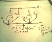
Let's say you have a copper conductor with one end attatched to the main ground reference point: If one has a ground node (say the ground for a particular stage's capacitor) and all the grounds of the stage that capacitor feeds are tied directly to that node: there is the current loop. Then you have to reference that node to whatever voltage you are calling your reference-- zero or otherwise. The reference connector is not a part of the current loop, and that connection from the node to the reference is not a current-carrying conductor, so how can you have an issue there as long as every stage is a contained loop and there is no current along the (voltage... not current) reference bus?
here is a grossly simplified example of what I am asking:
Attachments
HollowState said:
Well Jan, I must be blessed because I've never experiecned any of that. With a heavy #12 or #10 wire that is not excessively long it just doesn't happen. My busses are typically 6 to 8 inches long max. I suppose if one had a thin wire that wandered all around the chassis that could be a problem. Perhaps I should have emphasized proper wiring techniques of keeping things short, tight and neat with clean connections.
edit: Just read Tom's post. Very technically correct but pragmatically it's argumentative hyperbole. This isn't rocket science. If you use a good heavy wire buss with short intervals between circuit nodes (like 2 inches or less) you won't have problems. And if you do, something else is wrong.
Victor
Hi Victor,
I am sorry. My intent was not to get to the point of seeming argumentative. My intent was merely to provide information that I believed the original poster and others should be aware of.
I did say that a buss ground was "not as good" as a star topology. And that is true, technically, in terms of ground bounce. However, like many other things, making a judgment or design decision depends on how significant any effects might be, versus other considerations. That is one reason that I suggested simulation: so other people could try to judge the significance of the effects, for themselves, for any particular layout.
I certainly do agree that a buss ground, if short enough and thick enough, could function without significant ground bounce effects.
But, rather than having to worry about whether or not there might be a significant-enough problem, for others, I think that it is safer, for me at least, to advise to always use a star ground topology (or to at least present the theory involved, to try to enable people to decide for themselves).
aletheian said:here is a grossly simplified example of what I am asking: [/B]
(correction) Oops... there should be a resistor between those caps on the B+ rail in my sketch.
gootee said:
I certainly do agree that a buss ground, if short enough and thick enough, could function without significant ground bounce effects.
But, rather than having to worry about whether or not there might be a significant-enough problem, for others, I think that it is safer, for me at least, to advise to always use a star ground topology (or to at least present the theory involved, to try to enable people to decide for themselves).
To me, several long ground return wires to a star proved prone to pick up field noise from transformers and tubes. Practically, the short buss worked better. While very near to negligible parasitic resistance when very thick, it kept returns short and tactical. Its not only about zeroing bounce, there is a dirty environment around the earthing , too.
OK - I think I have a plan, but I would like to run it by everyone.
I will use an isolated terminal strip with a bare copper wire near my inputs. I will then run a wire from them to their respective local ground node I create near each tube, using another isolated terminal strip with a short piece of copper wire soldered to the terminals. Then from there to a single pt or star ground. What about my outputs?
I also have one transformer for each tube. I will tie all of the filter caps, and diodes to another local node, using the same techniques above and run one wire to the star from each supply.
I am using 12V regulator for my filaments, I will tie their ground to the star or can I run them from the local node I create for the tube signal grounds?
What do people commonly use for the star connection ( being my copper ring idea will not work ). I have some solder tags, would they work?
Again, I would like to thank everyone for the responses. I am really itching to start soldering, but I want to do it right the first time.
Gary
One way you could make the star connection is using ring tongue connectors, and a bolt, and one or two nuts. At least I think they're called ring tongue connectors. They look like a flat or toothed washer with a protruding solder lug. (And there are many similar types, with other kinds of wire connectors.)
Believe it or not, the real star ground fanatics even worry about in what order the connectors are placed onto the bolt.
Believe it or not, the real star ground fanatics even worry about in what order the connectors are placed onto the bolt.
aletheian said:I am trying to see what you mean about ground-return current, but a buss ground and a star ground with a reference bus are completely different.
Let's say you have a copper conductor with one end attatched to the main ground reference point: If one has a ground node (say the ground for a particular stage's capacitor) and all the grounds of the stage that capacitor feeds are tied directly to that node: there is the current loop. Then you have to reference that node to whatever voltage you are calling your reference-- zero or otherwise. The reference connector is not a part of the current loop, and that connection from the node to the reference is not a current-carrying conductor, so how can you have an issue there as long as every stage is a contained loop and there is no current along the (voltage... not current) reference bus?
here is a grossly simplified example of what I am asking:
If there really were "no significant current", then there would be no significant problem.
I'm not sure I understand your diagram. How is the current from the B+ supply getting back to the supply's ground? Anyway, at least the noise and variations of the B+ supply would cause current to flow through the capacitors, and then the buss, to the star point. I think I would want to also test it with at least the grid input resistors having their own separate ground references.
Personally, I think it would probably be good to try to use a "star power" topology, too, along with a star ground, and keep the power and corresponding ground conductors together, tightly twisting together each power feed wire and the ground return wire for it (and also twisting together reference-ground wires with the signal's wire for which they are the reference, if possible), if using point-to-point wiring, or running the PCB traces right on top of each other, on opposite sides of the board, if using a 2-sided DIY pcb. That should all also help in trying to keep the loop areas as small as possible, which should help to minimize field-induced currents.
HollowState said:
Well Jan, I must be blessed because I've never experiecned any of that. With a heavy #12 or #10 wire that is not excessively long it just doesn't happen. My busses are typically 6 to 8 inches long max. I suppose if one had a thin wire that wandered all around the chassis that could be a problem. Perhaps I should have emphasized proper wiring techniques of keeping things short, tight and neat with clean connections.
edit: Just read Tom's post. Very technically correct but pragmatically it's argumentative hyperbole. This isn't rocket science. If you use a good heavy wire buss with short intervals between circuit nodes (like 2 inches or less) you won't have problems. And if you do, something else is wrong.
Victor
Well Victor, that's funny, that you say you never experienced it. Just a few posts ago you said: "Also, the best ground point for the buss can be determined experimentally by connecting it to different points on the chassis while listening with a small speaked or phones for lowest hum level with no signal.". That appears to point out it is a real issue that you need to 'fix' afterwards.
Now in this post you say "My busses are typically 6 to 8 inches long max." and then you go on to comment "If you use a good heavy wire buss with short intervals between circuit nodes (like 2 inches or less) you won't have problems."
Seems to me this is inconsistent. Now, Tom's post is clear and explains the reasons why star grounds are better. I agree that to understand his post you really have to THINK rather than throwing around off the cuff, contradictory remarks. But then again, understanding often needs thinking.
But, if you feel he is in error, we all could learn from you pointing out what the error is.
Thank you,
Jan Didden
- Status
- Not open for further replies.
- Home
- Amplifiers
- Tubes / Valves
- Star ground help