The old fashioned way was to create an under-damped alignment and critically damp the vent.
GM
Okay, This sounds like a plan. And one that can be tuned/ changed to suit.
You can ignore the TH1.
OK, then really no clue what you're talking about as at a glance the left sim looked fine to me.
GM
Okay, This sounds like a plan. And one that can be tuned/ changed to suit.
Yep, the pioneers didn't leave us a whole lot to invent and had they figured out SS power first, we ~wouldn't have any speaker wise, but then we'd have missed out on all those beautiful sounding tube compression horn, single driver combos, etc..
Forgot this or do it with an impulse response test: Click Test | GM210 | Flickr
GM
Or you could give up back loaded designs.
i have done too much here and its just about dried up the fruit tree of ‘learning’ with all these pipes or BLH things...
the fun and curiousity got stiffer with ‘taped’ and then mire as ‘taped/compound’. But compound horn with an EXP flare proved to be way more interesting. So bad i was damaging equipment and drivers taking a look as it morphed i to a FLH/vented chamber with duct into the FLH and then just a tapped huge horn... full circle.
Now its back to chasing harmonics to exploit the passband in qw segments of the qw of fundamental... but as a ‘tapped’ the whole thing gets tricky all over again . So its a progression of CSA in segments of Fb length. but its hard/confusing to keep things positioned in the window of Horn response TH/TH1. and also be fair/accurate in the details if a folded segmented CSA path bei f traveled
Yep, the pioneers didn't leave us a whole lot to invent and had they figured out SS power first, we ~wouldn't have any speaker wise, but then we'd have missed out on all those beautiful sounding tube compression horn, single driver combos, etc..
Forgot this or do it with an impulse response test: Click Test | GM210 | Flickr
GM
Somehow i wanna get this turn to float🙂 maybe leaving the damping up to the second driver area wasnt enough. but it was easy to stick a bunch of polyfil in a closed end pipe and shove it in the big mouth(especially if its length was at a harmonic integer.. but then the mouth (response) seems to be smoother again as a result you wanna make it even bigger and longer..as excursion allows more too! . lol!!! We will never beat the need to fuel the Addiction, all this ‘bass’ and mid bass or infra bass or anything bass is a drug. Its powerful!
Last edited:
GM, that tester is better than mine🙂, i dont use a resistor. but i never thought to listen, I was just checking polarity... good one!
This is why i cant use ‘path’, i want to use the tapped drivers polarity shift point as a potent tool / advantage. so i shorten the end legs and add that back as a chamber to which all harmonic intervals are being represented and in such a way that they SUM quite nicely, but also can be seen in Horn response all the way up and the scale clearly. Lined up colums between each with defined edges.
So if we make blue a small CSA and yellow a bigger CSA
So if we make blue a small CSA and yellow a bigger CSA
Attachments
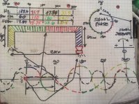
See that ‘signal strenth’ on the far right? gets all skewed with a taper or a flare, becomes a CAM LOBE of sorts? Or a twisted/knuckled rocker ratio? I dunno, but it screws up the ease of aligning sections( as colors ) to certain lengths that add up to the fundamentals result. but i have seen the flicker of that being possible??? I think i (Heard it?? ) I must do better or im stuck being annoyed with the stalmate of ‘Covid’...and thinking and wasting too much wood or time on the computer avoiding the ‘thinking’..
Last edited:


This is why i cant use ‘path’, i want to use the tapped drivers polarity shift point as a potent tool / advantage.
So if we make blue a small CSA and yellow a bigger CSA
Hmm, 'sounds' like you're trying to make a synergy concept pipe, so need to tap in drivers at certain points. I mean that's what a synergy horn does and when all the 'ducks' line up in a row you wind up with an impedance plot that starts at -180 deg at the low cutoff and +180 deg at the HF driver's upper end, the flattest impedance obtainable.
Never given it any thought, but maybe taps off the throat [chamber?] to feed taps along its length with the feed pipes tuned to ??
Really, you're way beyond me on this type stuff, I initially was primarily interested in intake/exhaust design, fiddling with audio as the knowledge base became available to me.
Anyway, good luck with it, hope you find a new way to do this or at least reinvent some lost 'art' like Tom and others have done.
GM
Synergy. I guess thats kinda where this went. I had (as usual) no tight focus
Or specific plan, instead many.
Take the 4th order qw pipe response for the TS parameters and ‘exploit its art-tributes with minimal damage or unreasonable stress/strain.
pipe segments and those together being a variety of contributing standing waves (by design) , i suppose?. With some guideance, some luck and great links to much more than ‘luck’ you make it fun Greg, thanks so much. I will pay it forward, pictures, patents and pressure waves. and even a coffee table with dual opposing a friend seems to be shuffling around to fit into a ‘size’ of box
Or specific plan, instead many.
Take the 4th order qw pipe response for the TS parameters and ‘exploit its art-tributes with minimal damage or unreasonable stress/strain.
pipe segments and those together being a variety of contributing standing waves (by design) , i suppose?. With some guideance, some luck and great links to much more than ‘luck’
you make it fun Greg, thanks so much. I will pay it forward, pictures, patents and pressure waves. and even a coffee table with dual opposing a friend seems to be shuffling around to fit into a ‘size’ of boxA little more fun for you, right up your 'alley' 😉, dude wants a double filter tapped open pipe simmed: diy double trapped vent
GM
GM
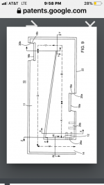
GM, those are closed stubs ("trapped" in the thread name, not tapped !)to damp standard bass- reflex port resonnances and a bit (even if he didn't realize) of his tall enclosure resonnance. I simed it in akabak 2 on a french forum.
Last edited:
Thanks! Understood, I meant 'open' in the sense that the tube the band-stop filters are attached to is an open pipe. As for 'tapped', technically they are, a source of confusion these days due to 'tapped' horns, etc.. 😉
GM
GM
Last edited:

Thats really cool!
A very restricted to a location, another version, using horn response: offset driver, offset port to exit is two chambers at start and ‘finish’, a lot of ways in that sim to kill pipe resonances or promote them.. tapped horn, with Throat ported entry. Venting internally into the system to ‘infinite tapered’ dead ends, a very long, thin and stuffed qw or hw absorber version is that way too it seems.
A very restricted to a location, another version, using horn response: offset driver, offset port to exit is two chambers at start and ‘finish’, a lot of ways in that sim to kill pipe resonances or promote them.. tapped horn, with Throat ported entry. Venting internally into the system to ‘infinite tapered’ dead ends, a very long, thin and stuffed qw or hw absorber version is that way too it seems.
For an Fb of 40hz i used a constant CSA and split the orange in half -‘as it lands as a 180 degree fold of that in distance. Yellow is offset driver position and green is the large chamber to exit after the driver.
In horn response the fold isnt implemented its the Vtc/ Ap1, change. or it would be. but its obviously spread harmonic intervals of 3n with out. its a not easy to ignore a basket diameter or variety of details can derail this phase aligned more and more... but the looking glsss isnt blurred with a taper or expansion rate...
In horn response the fold isnt implemented its the Vtc/ Ap1, change. or it would be. but its obviously spread harmonic intervals of 3n with out. its a not easy to ignore a basket diameter or variety of details can derail this phase aligned more and more... but the looking glsss isnt blurred with a taper or expansion rate...
Attachments
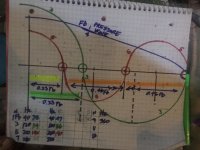
The orange areas split as a CSA shift or not, at a fold will be how that gets dispersed. (0.46 Fb in Qw) at the CSA, plus the same, ran thru a dual spring rate calculation is roughly what i used. But it was easier to find a realistic value for S using Vas in the TS parameters and use it the entire length of the Fs(for Qts) with a single assumed fold. The driver was cooperative... Then you can size the other side to clear the pole vent and adjust for ‘realty’ in a sim or otherwise.
If i repeat the process in many variety of dual chamber or similar compound or series the same results from the same generic sizes in progressing air mass segments happens. (it seems) so far.
If i repeat the process in many variety of dual chamber or similar compound or series the same results from the same generic sizes in progressing air mass segments happens. (it seems) so far.
- Home
- Loudspeakers
- Subwoofers
- Standing waves in folded qw pipes?