The pipe will always have a velocity maximum at the end since the opening should have the same pressure as the surrounding room.
At the fundameltal you will have a pressure maximum at the closed end.
When the frequency increases the pressure node will "walk" towards the open end. When the pressure node finds a corner, the corner will "help" the standing wave.
This conundrum we can skew? Or make ‘best’ by how we layout the folds
Maybe it can be seen when looking at the taper or expansion shapes affect and resulting tuning hz?
I believe you need Akabak to simulate that. It is hard enough to understand a pipe with a single driver 🙂
Also when a pressure maximum passes over the driver, the output will shift 180 degrees.
If we take your setup as an example, above the fundamental the pressure maximum will travel towards the second driver. But the drivers will cancel each other out. If you phase shift one driver you will see that you will get more output when the pressure maximum is between the drivers, but when it passes over the second driver they will start cancelling each other out.
If we take your setup as an example, above the fundamental the pressure maximum will travel towards the second driver. But the drivers will cancel each other out. If you phase shift one driver you will see that you will get more output when the pressure maximum is between the drivers, but when it passes over the second driver they will start cancelling each other out.
Gregs thread response to the Bose wave cannon and the square antennae shape was quite something! Even in a sim its partly shown ..
But the compound pipe Lost to a taped design now thats helping make more sound, but what about all this harmonic interval stuff too?
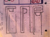
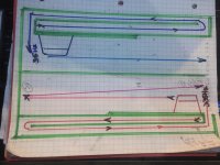
All of these(pic) have a unique sound to the upper subwoifer freqs. ive made a couple of each and various 4th order versions. I think if i had the ‘folded’ segments closer to making there own fundamentals as a integer of the longests Fb, then thats a lot of magic in certain areas of the bandwidth?
But ive missed the mark or ive skewed that alignment up over and over(some way widde than others) and taper/flare, or different lengths has always been uneven or an issue?
Can i still tap this fir the help in moving all this air in a series or similar manner? And if i keep it inside folded in a cabinet instead of ‘path’ seoerstiom
N of the Square antenna shape is the missing link to 3/6/9/12 gone?
But the compound pipe Lost to a taped design now thats helping make more sound, but what about all this harmonic interval stuff too?
All of these(pic) have a unique sound to the upper subwoifer freqs. ive made a couple of each and various 4th order versions. I think if i had the ‘folded’ segments closer to making there own fundamentals as a integer of the longests Fb, then thats a lot of magic in certain areas of the bandwidth?
But ive missed the mark or ive skewed that alignment up over and over(some way widde than others) and taper/flare, or different lengths has always been uneven or an issue?
Can i still tap this fir the help in moving all this air in a series or similar manner? And if i keep it inside folded in a cabinet instead of ‘path’ seoerstiom
N of the Square antenna shape is the missing link to 3/6/9/12 gone?
Attachments
Also when a pressure maximum passes over the driver, the output will shift 180 degrees.
If we take your setup as an example, above the fundamental the pressure maximum will travel towards the second driver. But the drivers will cancel each other out. If you phase shift one driver you will see that you will get more output when the pressure maximum is between the drivers, but when it passes over the second driver they will start cancelling each other out.
Yes! This very thing can be heard and shown. The top and bottom layouts are nearly identical if given the same lengths and csa dustributed. But the offset(bottom) is causing a out of pass band narrowing thats an obvious ad a phase shift occurs at the point of exit (and seen in sim).
I think ive repeated this in the middle example, but ive given the result already its now just propagating a wave thereafter(tapped) and i think its missing the high frequency (ghosts) i clearly hear in the bottom version as it disturbed things like no other around the room or anywhere i took it(which weren't such a issue with any others (higher frequnve tune in that shorter chamber has artifacts??)
I think i can improve upon the middle. Align the folding to intervals of the main Fb, but what to do? the results in sim say the same thing. These are all so very related. (Sim doesnt show that folding component and its interesting ‘advantage’ in science, nit necessarily ‘perfect monitor speakers’.
I tend to chase things that might be impossible or never ‘ideal’. i dunno if thats an issue here or not, but the help and guideance is phenominal to explore and try and impliment!
An intersting thing happens in these. And it was the reason i had ‘optional’ or ‘second’ drivers drawn on the opposite end of the larger segments. the high frequency bleeds out of those and isnt well represented in much of a sim as it seems to be in reality. after quite a few attempts to eliminate standing waves, i thought about ‘using’ them or the strategy of placement at useful intervals.
i think between myself and a few local diy guys weve tried (experimented) with nearly each offset driver, splayed driver, and stub. prettt much running into exactky what you pointed out in the partial cancelation and phase getting flipped and flopped band and forth (defeating itself along the way).
The one that stood out for me seemed to be the ROAR or the backward HF chambered paraflex. Both have similar layouts but series or parallel /both...
I think it night just come down to dropping expirimental closed end pipes /absorbers into a big ROAR and using integers of the Fb in chunks (3/4, 5/4,etc )to dance around the response until it results from stimulating at 3,6,9 and 12 positions, and ‘evenly’.
There are Ghosts in these boxes. HF ghosts. Its very strange. Interesting and kindof fun trying to figure it out(i dont think people care, they just STUFF it away if they hear it??) friend has a sscond driver at velocity max for the offset driber TL(typical) and has cancelld much and created other... its pretty interesting.
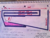
Hard to say if the pink area(polyfilled) is useful or wasted space in a sim but i was considering two of these (mirrored) with a shared exit at the very end. Whats hard to tell is if a flare rate keeps the upstream Fb or changes it and what to use for lengths if striving to keep the harmonic intervals as folding or segmebt/stub lengths for the system Fb
Attachments
OK, you have a damped band stop filter, but tapped in where along the horn's acoustic axial length and what peak you're targeting?
GM
GM
Last edited:
All of these(pic) have a unique sound to the upper subwoifer freqs.
IF I understand your primary 'dilemma' [big IF it lately seems and still not sure what all the other 'dilemmas' are], I previously posted one way, giving what I thought a sufficient hint how to solve for others, but apparently not, so going back to the beginning; Harry Olson 'solved' it in the mid '30s without using a 'tap' in his original studio monitor BLH patent, though not the first BLH patent per se as some folks believe[d], but to 'solve' W.E.'s 'issues' [or so I concluded based on patents, DIY POCs]: US2224919A - Loud-speaker
- Google Patents
GM
Pick one? I cant... and ive already been convinced this sound is ‘fun’, i have a couple of these in flared or tapered.
But the high frequency stuff... it sneaks out that mouth, and its not possible to ‘manage’ iit very well with XO or dsp. Im trying to do it the old fashion way (for nostolgia), align all the standing waves in folding with the fundamental as its harmonic lengths would be.
The price to pay for this large open exit seems to be double edged sword. but in a ‘room’, not outside, it is often (ambiguously there even moreso. Kind if annoying, but at the same time, very interesting to ‘fix’. But using which layout and breaking it up into folds that add up as 3,6,9 and 12 (no square wave antena mods inside ‘tapped’? That ‘path’ spread could be done in a few ways, but they leave a huge part of the process out in the ‘room’. I dunno if thats gonna work? I dont have much faith in predicting that?
Attachments
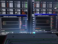
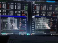
These are the sims from above. red is the right hand examples and the large chamber is stuffed. The blue isnt. i also need to determine if Fb requires a triple fold in the long skinny to suit the harmonic scenario based on Fb(the wave cannon thread you shared Greg).?
Attachments
IF I understand your primary 'dilemma' [big IF it lately seems and still not sure what all the other 'dilemmas' are], I previously posted one way, giving what I thought a sufficient hint how to solve for others, but apparently not, so going back to the beginning; Harry Olson 'solved' it in the mid '30s without using a 'tap' in his original studio monitor BLH patent, though not the first BLH patent per se as some folks believe[d], but to 'solve' W.E.'s 'issues' [or so I concluded based on patents, DIY POCs]: US2224919A - Loud-speaker
- Google Patents
GM
1937! Wow😱 this is amazing archived and beautiful!
Hmm, had to look up TH1, haven't kept up with all the new options. Seems the only difference is adding a vent to the TH terminus, but what you've written implies something completely different to me, so guess I'm the most clueless one here.
Guess I'll play with it as time permits, but got a bunch of others to respond to first and seems like whoever wanted the option would be able to help you.
GM
Guess I'll play with it as time permits, but got a bunch of others to respond to first and seems like whoever wanted the option would be able to help you.
GM
But the high frequency stuff... it sneaks out that mouth, and its not possible to ‘manage’ iit very well with XO or dsp. Im trying to do it the old fashion way (for nostolgia), align all the standing waves in folding with the fundamental as its harmonic lengths would be.
The old fashioned way was to create an under-damped alignment and critically damp the vent.
GM
Hmm, had to look up TH1, haven't kept up with all the new options. Seems the only difference is adding a vent to the TH terminus, but what you've written implies something completely different to me, so guess I'm the most clueless one here.
Guess I'll play with it as time permits, but got a bunch of others to respond to first and seems like whoever wanted the option would be able to help you.
GM
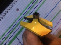
You can ignore the TH1. It was only there, as you said, for playing with a mass loaded end cap(a buddy wants to stick a couple of these into a coffee table and for HT. I tried it previously and ir was great. I used a huge thumbnail round over bit to smooth out the terminus as it otherwise was getting a bit noisy)#
Attachments
- Home
- Loudspeakers
- Subwoofers
- Standing waves in folded qw pipes?