Stan Curtis - MPSA-06 _ MPSA-56
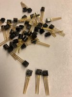
For those aficionados who just need to have the originals.
I bought these a couple of months after the article came out. I think it must have been -86. Never got around to build one myself. As can be seen they are the "good" ones with golden feet.
If there are any interest I could make up a package for a two amps.
Nope, I confused it with my second marriage, it was autumn -81.
Regards
R
Attachments
Last edited:
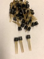
For those aficionados who just need to have the originals.
I bought these a couple of months after the article came out. I think it must have been -86. Never got around to build one myself. As can be seen they are the "good" ones with golden feet.
If there are any interest I could make up a package for a two amps.
Nope, I confused it with my second marriage, it was autumn -81.
Hello
Do you still have the transistors for sale ?.
Regards
R
Stan Curtis's iconic 1980s 60W Class A amp and pre-amp continue to attract interest well into the 21st Century. In the intervening years, vinyl had almost disappeared before making an extraordinary return to popularity, other source output levels have at least doubled (or more) in voltage, and streaming is achieving a previously unheard-of acceptance deep into the heart of the audiophile world. My interest is in adapting Mr C's original design to bring it up to date for use with these modern sources and, where necessary or appropriate, using modern equivalent components to further enhance the electronics (NB, not the fundamental circuitry) of this well-loved design. This forum, along with 2 others I have found on this site exclusive to this amp, reflects a wealth of experience from people who have built, adapted and generally tweaked it, so I hope I can draw on this experience to make the right decision, and receive some guidance along the way.
Project broad outline:
1. Where possible, use original components unless it is clear modern equivalents are better.
2. Create a new pattern PCB (using Autodesk Fusion 360 Electronics Library) to address some of the issues raised in subsequent reviews (eg stability surrounding the long wires in the power amp, adding balanced inputs/outputs, a soft start circuit etc)
3. Add suitable Aux inputs for modern source equipment.
4. Remove/rethink the value of the balance control.
...and my immediate question, to start the ball rolling: Nowhere is there definitive guidance on the specification of the power amp transformers, save the comment that they are 'substantial' 500VA toroidals. 2 secondaries are required to provide (after rectification and smoothing) +/- 40VDC high current lines and +/- 50VDC low current lines, and I cannot work out how this would be achieved looking at the PSU circuit diagram (please see page 9 of this link). Can anyone translate this to modern-day equivalency please?
I've always had great interest in building this amplifier. Seems like a project thats not for the faint of heart...it's perfect! Take a look at Nelson Pass's A75, It uses a regulated 50V for the front end, and an unregulated 40V for the output stage.
FIRST WATT
-john
FIRST WATT
-john
In high power amps I have usually specc'd low magnetic fields. many toroidals run at full whack to keep the size/cost down, but Canterbury Windings provides a 70% max field option, which generally tends to run things cooler and more efficiently, which is what I required.
Normally for 40V you would use 30V AC (45 peak out light load) and the Curtis psu just needs an additional +/-10V winding tacked onto each end of the main primary so the spec. should look something like 10-30-0-30-10 with the 10V windings rated at perhaps 1A and the 30V windings at 4A DC or 8A for stereo. The AC current rating needs to be greater than the DC due to the huge pulse effect of large smoothing caps.So it's at least a 250W unit for mono or 500W for stereo. FOr continuous ratings at 4A (I assume you would run it at this from what I've read) I'd probably spec. 5A or 10A (300W/600W) if I were purchasing a transformer.
You can generate the 50V from voltage doubling the 40V rails and adding a local regulator which would allow you to use a COTS transformer with only a 30-0-30 output.
Or as some suggest, cheat and wind an additional couple of 10V windings over the top of the completed unit yourself!
(Although I've done this in the past it is not a practice I would actually endorse due to ensuring that the wire is equally well protected as the original from physical damage in the main).
I remember this amplifier from when I was a young one!
I was very much intrigued but never got around to build one.
Later, when I started Linear Audio, I commissioned Stan to write a column in each issue! Very read-worthy!
Just reviewed the 'after article notes' and found something which may actually bite you.
Stan said:
7. The heatsinks should be chosen to allow the amplifier to run at a case
temperature of between 40 and 50ºC. Since each output transistor dissipates
40W, each should be bolted to a heatsink having a rating of less than 1ºC/W.
Actually, using a 1ºC/W heatsink with 40W dissipation increases the temperature with 40ºC above ambient. If your room temp is 20ºC your heatsinks will be 60ºC, and the transistor junctions will also be 20ºC higher. I would use heavier heatsinks, like 0.6ºC/W or so to be on the safe side for hot summer days.
Jan
Gents, good evening, and thanks for your replies.
If I could just address John Ellis's post first - John, I think we are coming to a similar conclusion but from slightly different directions. If from the image on page 9 of my link above (sorry - new to this and can't yet find a way of uploading an image from my computer!) we count the secondary windings from the top, we get the figures (not accounting for load) of +35.5, +28.4, 0, -28.4, -35.5, giving us the 2 x 40V and 2 x 50V outputs required. Option 1 would seem to be that I arrange for a 63.9 - 0 - 63.9 secondary with taps in each 'side' to give the split as shown above. Wasteful given that I suspect the 50V rail feed doesn't need the wire gauge the 40V rail feed does and perhaps just that little bit over-complicated. Option 2 would be providing a 28.4 - 0 - 28.4 secondary, with a high current capability, and an additional secondary at 100 - 0 (as no zero rail seems to be necessary in that part of the circuit) using a lower-current winding. I don't really want to use a regulator if possible. Would that scratch the itch? Naturally, these would then be rounded up to take account of load.
John @ MEGA_Amp - thanks for your post. Sometimes I genuinely wish I was a little more faint of heart, as this is a big project! I'm feeling confident about the support already, though, so thank you 🙂
Jan - thank you too. I had spotted that too but got my original sums wrong! and it's now a case of balancing off how warm I can have it run with the aesthetics and sheer practicality (not to mention cost!!) of all those fins! I'm really not into the 'weird spikey spaceship prop from a 1950s Flash Gordon film' look. My current thoughts were the Wakefield-Vette 423As which advertise 47 degrees at 50W so I'd be mid-50s even in a cool room! I would welcome recommendations of a suitable alternative.
Last edited:
Correction to my last - there additional secondary would need to be 35.5 - 0 - 35.5 or, if the negative rail can be achieved without a zero tap, a 70.1 - 0 winding.
YOu could always use two transformers - a big toroidal for the high power stuff and a small auxiliary for the 50V rails. I don't think it looks as elegant and it is a bit more inconvenient to wire two transformers up. I've always used voltage doublers for this task (the overwind I mentioned was not for an audio amp). The regulators can be on the same PCB as the doubler caps/diodes.
Another reason I suggest you may want to consider a regulator for the low power/high voltage rails is that in class A there may well be considerable hum on the main power rails.
Stan's design looks filtered/smoothed but class A usually benefits from as much additional filtering as possible.
Just checked Canterbury windings - the person running it is semi retired and only doing a few now, but still in business. A custom spec design with your additional windings would be ideal because, as you say, the high voltage rails don't need a lot of current.
Hello Marra .. thanks for the heads up
Not far from my location .... I will update my build later over the weekend
But does anyone have the original transformers for this project otherwise will get some new ones made by Canterbury transformers
Not far from my location .... I will update my build later over the weekend
But does anyone have the original transformers for this project otherwise will get some new ones made by Canterbury transformers
Normally for 40V you would use 30V AC (45 peak out light load) and the Curtis psu just needs an additional +/-10V winding tacked onto each end of the main primary so the spec. should look something like 10-30-0-30-10 with the 10V windings rated at perhaps 1A and the 30V windings at 4A DC or 8A for stereo.
You can alternatively add a second transformer with 10-0/10-0 outputs (two separate windings; not 10-0-10) to achieve this.
Transformer schematics
If from the image on page 9 of my link above ... we count the secondary windings from the top, we get the figures (not accounting for load) of +35.5, +28.4, 0, -28.4, -35.5, giving us the 2 x 40V and 2 x 50V outputs required.
If from the image on page 9 of my link above ... we count the secondary windings from the top, we get the figures (not accounting for load) of +35.5, +28.4, 0, -28.4, -35.5, giving us the 2 x 40V and 2 x 50V outputs required.
Since my post, including the quote above, (still can't get the hang of this site for posting!) it's become clear I did not interpret the Transformer schematic correctly, and @john_ellis was absolutely bang on the money with his suggestion. @jamesfeline - many thanks for your suggestion about Canterbury Windings, but I contacted Terry Monaghan who told me he is retiring (fully) at the end of December so is not taking on new clients/work. So, I think I'll be continuing with Audiophonics.fr who provide an on-line bespoke toroidal ordering service. This means I'm obliged to opt for the 2 secondaries route - the main hi-current rails being from an 30-0-30 winding and the low-current additional winding being either a 38-0-38 or the 2-wire alternative (haven't decided, although I think the latter will give me everything I want). All pending a little more research into understanding Transformer Regulation and likely causes of voltage drop within the PSU. The inner geek in me wants to get the rail voltages as accurate as I can, even though I instinctively know I don't need to.
Last edited:
You can always use Sowter transformers but not sure if they do toroids ? worth a phone call though
SOWTER AUDIO TRANSFORMERS WORLDWIDE SHIPPING
SOWTER AUDIO TRANSFORMERS WORLDWIDE SHIPPING
- Home
- Amplifiers
- Solid State
- Stan Curtis 60W Class A