Charles: Yes if you have any articles handy email them to me at xenon11( at )walla.com (big 3gB email)
Im particularly interested in how the THD was reduced by ~12dB <50hz with the original acebass system. But above 50hz is much the same or slightly worse.
Im particularly interested in how the THD was reduced by ~12dB <50hz with the original acebass system. But above 50hz is much the same or slightly worse.
The Audio Pro B2-50 subwoofer was the forerunner to the modern day compact active subwoofer.
It could produce a maximum SPL of 96 dB into half space at less than 3% distortion from two 6 inch drivers mounted in a 50 liter enclosure tuned to 20Hz and driven by a total of 80 watts of power !!!
The distortion reduction comes about by the fact that two drivers are mounted in push pull arrangement. Also when the synthesized mechanical parameters dominate the real parameters there is a distortion reduction mechanism and the tests do confirm this !!
At the same time Audio Pro did make a full range active system called the A4-14 which was flat down to 30Hz in a 12 liter box and 40 watts of power !!!
http://www.mellanstrommen.se/qbaze/a4-14front2.jpg
These days much more power is required to meet the demands of home theater and I believed that Audio Pro did make more powerful models including some semi professional versions.
snoopy said:The Audio Pro B2-50 subwoofer was the forerunner to the modern day compact active subwoofer.
It could produce a maximum SPL of 96 dB into half space at less than 3% distortion from two 6 inch drivers mounted in a 50 liter enclosure tuned to 20Hz and driven by a total of 80 watts of power !!!
The distortion reduction comes about by the fact that two drivers are mounted in push pull arrangement. Also when the synthesized mechanical parameters dominate the real parameters there is a distortion reduction mechanism and the tests do confirm this !!
At the same time Audio Pro did make a full range active system called the A4-14 which was flat down to 30Hz in a 12 liter box and 40 watts of power !!!
http://www.mellanstrommen.se/qbaze/a4-14front2.jpg
These days much more power is required to meet the demands of home theater and I believed that Audio Pro did make more powerful models including some semi professional versions.
Snoopy,
Since you are very familiar with this, so we can put this in perspective with directservo patent. Our directservo patent achieves the same results in changing T/S parameters as Stahl's approach without its disadvantage and then add some more advantage. All servo, no matter if it is accelerometer-based, sensing coil-based, they all achieve the effect of changing the "apparent" T/S parameters of drivers. In the case of Velodyne/Paradigm, it is mostly adding moving mass, and in our sensing coil based approach, it is adding resistive damping to the system. Since you are apparently interested in all these subjectives, it shouldn't surprise you that they are all related to one another.
If you are curious enough, I first time hear Audiopro when I was in high school. I didn't have the chance to read Stahl's paper till I was in graduate school (for Electrical Engineering). I read the paper with fascination. I started to experiment with it and soon I found a serious problem in the approach -- the negative output resistance to cancel the voice coil resistance. To get good results, I need to achieve near perfect cancellation. I can always get loud power-on surge, an indication that the system can be marginally stable. In addition, as Mills and Hawkford pointed out in their JAES paper "Transconductance Power amplifier Systems for Current-Driven Loudspeakers", JAES volu 37, No 10 1989 Oct, the cancellation effect is heavily affected by the voice coil temperature. For instance, if the DCR of voice coil is 4ohm, the negative resistance is -3ohm, the net is 1ohms. If the temperature rises to 200c, the resistance would be 6ohms and the negative resistance is still -3ohm, so the net is now 3ohms. A 3 times amplification of voice coil resistance fluctuation. I spent time searching all techniques for temperature tracking and experiment with them and no good results. So I finally gave up and start experimenting with sensing coil approach (at that time, using a dual voice coil driver).
After a lot of work, I then found with both sensing coil feedback and current feedback, I can achieve the same results as what Stahl's has done and more. All of this is done without resistance cancellation. All feedback are negative feedback. No positive feedback at all. Power on surge is minimal even without a relay. Unconditional stable when amp is in clipping. I can write close-form equations and explain how the apparent T/S parameters are changed with the servo feedback and build a model to explain what is the similarity and difference between accelerometer-based approach and point out in circuit theory term, why accelerometer based approach all have a unwanted resonance at subsonic frequency range. The Q value is so high that when I pushed the cone of my ULD15-II, the cone will just literally warble in and out at about 0.5hz frequency and wont stop for a good 5 seconds. From the model, it can easily show that the Q value of the resonance is very high and the frequency is also very low. The root cause is the acceleration signal is not compatible with the DC blocking circuit in the sensor amplification circuit, feedback and the amplifier. This transient response occurs when I push the cone, it can also happened when the system is seriously distorted, such as amp clipping. So Velodyne's approach is to use an AGC (automatic gain control) limiter to let the amp never go into clipping. This is very different from soft clipping limiter. Because AGC limiter does not produce harmonic components so it can fool all THD equipment. As in this resport:
http://www.avtalk.co.uk/forum/index.php?t=msg&th=18355&start=0&rid=0&SQ=0.
That a DD-12 can never output more than 87db at 20hz no matter how hard you push it. And yet a lot of people will misquote and say DD-12 has less than 3% distortion at 105db at 20hz because they only look at one graph at a time. And who should be blamed for quoting that? Velodyne and they are literally cheating the system.

So in practical use, does AGC create a problem? Yes. One of my early customers mentioned to me that his Velodyne servo sub produces very weird sound for organ music. Let us say there is a supposedly 110db 20hz signal arrives, the AGC immediately limit the output to 100db. So that is a 10db attenuation at 20hz. Supposed at next moment, the supposedly (without AGC) output is immediately reduced to 100db, the slow response time of AGC would actually produce 90db (100db-10db=90db) sound, not 100db, even though the sub is capable of 100db at 20hz. It takes a finite time (less than a second) to the AGC to remove this added attenuation. Now whether the next low note arrives before the recovery or after recovery actually produces the note with different amplitude. The result is like it is played by a person who don't know what "fff" and "p" is in the music.
Now put everything back in perspective again, Stahl uses push pull to achieve distortion cancellation for even order harmonics. Velodyne also do similar thing with their push-pull motor design. That is one of the main reason the distortion number from Paradigm is very bad compared to Velodyne. For us, we can do that with two drivers. In addition, we don't feel compelled to reduces 2nd order distortion. If my customers are really bothered by it, I can add a distortion cancellation circuit in the servo to reduce 2nd order distortion (the patent has been filed). But that is another subject. BTW, I do have a Ph.D degree in EE (from USC, yes Trojans). So please, do ask reasonable questions.
rythmikaudio said:
(the patent has been filed).
Hello rythmikaudio
What is the Patent number of the direct servo .
PHEONIX said:
Hello rythmikaudio
What is the Patent number of the direct servo .
PHEONIX,
I do not give away patent numbers on the forum for several reasons. It is also a practice recommended by patent attorneys, and books like "Patent it yourself" by Pressman. However, I can sent out patent number on individual basis. I have sent you the patent number via email already. Similarly, anyone interested in the patent can me email and I will send out the number via email. For those who don't want to do it this way, with due diligence, they can also find the patent numbers from our website (not from the text though).
Brian
Hi
I've still got an Audio Pro B2-50 subwoofer somewhere. Don't use it anymore, though - it sounds awful, very muddy compared to a good IB /closed box sub.
I've still got an Audio Pro B2-50 subwoofer somewhere. Don't use it anymore, though - it sounds awful, very muddy compared to a good IB /closed box sub.
rythmikaudio said:
PHEONIX,
I do not give away patent numbers on the forum for several reasons. It is also a practice recommended by patent attorneys, and books like "Patent it yourself" by Pressman. However, I can sent out patent number on individual basis. I have sent you the patent number via email already. Similarly, anyone interested in the patent can me email and I will send out the number via email. For those who don't want to do it this way, with due diligence, they can also find the patent numbers from our website (not from the text though).
Brian
Pheonix,
Hope you enjoying reading the patent 🙂 Now the patent is not about how to reduce the distortion, rather it is about how to implement a stable servo system. Someone with good engineering background can see what else can be achieved with such arrangement. For a long time, I haven't shared with anyone on how to explain the distortion reduction in such scheme. I do think it is time now as I am working on a servo midrange system and the initial result is quite good. The advantage of servo is not just on subwoofer. However, we do seem to have different of thoughts in terms of what can be qualified as "servo". Some even say a servo for vented box is not servo. I hope through the following explanation, we can find a better common ground in that regard.
If we look at the equivalent circuit of a woofer, the voltage drop across it is the sum of IR drop across voice coil resistance and the back EMF which is B*L*v and v is the velocity of the voice coil. This B*L is also called BL profile of the motor. In other words Vsp = I*Rdc + B*L*v, where Vsp is the voltage cross the speaker terminals and Rdc is the voice coil resistance, and I is the voice coil current. Let us ignore voice coil inductance for now.
Most people misunderstand that as long as B*L is perfectly linear, there will be no distortion. That is far from truth. This is because the IR drop component is still in the equation. While Vsp is distortion free, but unless I*Rdc is also distortion free, we cannot ensure B*L can guarantee any distortion free operation. To see how that happens, let us assume the B*L value is perfectly linear. But the spider compliance is not. There are all sorts of other source of distortions: hysteresis and nonlinearity in surround, enclosure internal reflection, ..etc. In order to maintain linear velocity, that means the speaker current cannot be disortion free in that it needs a distortion component in the current to counteract these distortion source. However, Vsp is distortion free, that means the disortion component in I*R will cause an opposite sign but equal in magnitude in B*L*v. That is where the nonlinear component slips into the system. That additional nonlinear velocity will cause a reduction of the distortion current iteratively until the iterative feedback of these components is stabilized. But the source of distortion is from I*R. A smaller I*R is good. In addition Rdc is not a constant value, it is a resistor made of copper or aluminum with very high temperature coefficient (0.3%/C).
If you read the patent, you will realize the servo system's equivalent circuit is very similar to the above picture, except:
1) The B*L is not from driver coil, it is from sensing coil, so we can improve the linearity of sensing coil (for instance, using longer winding length, and based on that I can say all experiments based on off-the-shelf dual voice coil drivers would see very little improvement).
2) The new Rdc value is only 1/3 of normal voice coil resistance.
3) The temperature coefficient of the new Rdc is same as the current sensing resistor. That is, if we use a 50ppm/C resistor, the new Rdc would have the same temperature coefficient. That is far better than a 0.3%=3000ppm/C that regular voice coil has.
In particular, the fact of 2) is that it can reduce all sorts of distortion in the system by approximately 1/3x based on our discussion. This includes linear distortion, nonlinear distortion, static and dynamic distortion.
Now accelerometer based approach does have a very small Rdc in the servo equivalent circuit. But that actually provides very little damping to the system and the stability is very marginal. So all scheme that will remove the temperature coefficient of voice coil resistance, and give rise to a smaller Rdc is servo even though one can see the smaller the Rdc, the lower the distortion. It is a balance of how much distortion we'd like and how much stability we'd like to sacrifice. Lastly, the above analysis can apply to all frequency range. Servo should never be limited to just subwoofer.
Hi
I've still got an Audio Pro B2-50 subwoofer somewhere. Don't use it anymore, though - it sounds awful, very muddy compared to a good IB /closed box sub.
Maybe you should go through it and change the caps. They are probably on their way out after this amount of time 😉
Having said that, it is true that a good sealed box design will exhibit a better transient response than the 6th order response of the B2-50. The 6th order vented box design uses an auxiliary second order high pass filter in order to limit cone excursion below the vent resonant frequency so it should exhibit less mudiness and intermodulation distortion than some unfiltered vented box designs of the same size and power of the B2-50.
regards
Trevor
I´m trying to resurrect a B2-50 from the dead should be doable with the service manual.
I´m really curious how it will match up to my 4x8 inch infinite baffle subs that go straight down to 10Hz (max spl at 20Hz is 105dB with 2% thd).
@ Dirk95100
Be nice if you could & post the results 😉
Also thanks to everybody else who's contributed to this thread over the years 🙂
Be nice if you could & post the results 😉
Also thanks to everybody else who's contributed to this thread over the years 🙂
@ Dirk95100
Be nice if you could & post the results 😉
Also thanks to everybody else who's contributed to this thread over the years 🙂
I will post the REW curves.
Hi,
FYI: Translate this using Google:
Loudandproud musik med nrvaro
b🙂
I had a good laugh when translating...If there is something unrecognizable: Post and I will translate..
FYI: Translate this using Google:
Loudandproud musik med nrvaro
b🙂
I had a good laugh when translating...If there is something unrecognizable: Post and I will translate..
Ace Bass according to K.E Stahl
My first post, on any forum.
I just came across this , and I bought the paper after I read an article in some "Elector" book "Luidsprekers Fabels en Feiten" a couple of years ago .
I owned a JBL K140 and gave it a try .
The results are amazing !! It goes down to 20 Hz in a 57 l small cabinet and the SPL is good enough for my 60 square meter living room even with my high SPL 3839 Tannoys as fronts . I designed the circuit boards myself and used a Classd 400 Watt Amp from the UK as Amp . I have friends with very expensive subwoofers , but there all less capable ! ( The subwoofers🙂
If anyone is interested I will post the schematics and PCB design .
Cheers,
Rens
Yes please, I'm interested.
K140 Subwoofer
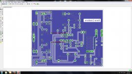
The schematic and board are designed in Eagle , you can download it for free at CadSoft - Home of CadSoft EAGLE PCB Design Software- Best PCB Design Software . I'll try to add some screenshots .
The Opamp used is a quad opamp OPA 4227p .I have to look in the schematics , I build it about 10 years ago or so . I changed the Amp from 150 watts to 400 watts in the recent years . The external connectors are connected to a PIC for DC protection , delayed on and quick off and infrared remote control . I look up that scematic tomorrow and take some photos . I must have some measurements files somewhere as well .
Attachments

Pictures
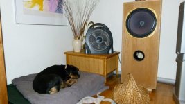
Just made some pictures of the sub and its amp .
The Rottie pup is not very happy when we play a DVD or Blueray 🙂
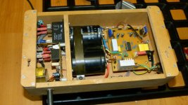
The reflex tube is folded externaly under the sub and made of 11 cm PVC tubing , tuned to 20Hz . The amp is mounted on the back of the sub with the IR "eye" just above the subs surface .
If I remember well , the Zeners in the schematic in the previous post are the wrong way around .
The transformer in the pics is a 500 VA 45-0-45 V AC .
Cheers ,
Rens
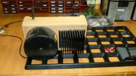
Ps Last Pic is my new project , 5 L15D classD , Emotiva UMC-1 and waiting for Christi's SMPS 1000
Just made some pictures of the sub and its amp .
The Rottie pup is not very happy when we play a DVD or Blueray 🙂
The reflex tube is folded externaly under the sub and made of 11 cm PVC tubing , tuned to 20Hz . The amp is mounted on the back of the sub with the IR "eye" just above the subs surface .
If I remember well , the Zeners in the schematic in the previous post are the wrong way around .
The transformer in the pics is a 500 VA 45-0-45 V AC .
Cheers ,
Rens
Ps Last Pic is my new project , 5 L15D classD , Emotiva UMC-1 and waiting for Christi's SMPS 1000
Attachments

Hi doctordata,
Now, there's a happy dog.
This looks like very nice work, would you mind sharing the Eagle files?
Regards,
Now, there's a happy dog.
This looks like very nice work, would you mind sharing the Eagle files?
Regards,
My first post, on any forum.
Hi doctordata,All
2cents:
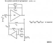
Even if your design do not entirely resemble an ACE-Bass amp you've done a great variant on this theme : I,ve noticed Your design seem to be able to alter the moving mass and damping but not the springiness (compliance) of the system.?
That is you control the upper FR boundary while the lower end is solely dependent on the your low-pass filter at the input and the Q setting using the built in negative output resistance feature.
FYI if not known: Here are two links to similar threads to this one,but the first at least cannot be found here down below in the: 'Similar Threads', I find this to be odd.
ACE-bass amplifier design:
http://www.diyaudio.com/forums/subwoofers/104447-ace-bass-amplifier-design.html
and:
http://www.diyaudio.com/forums/multi-way/83982-enclosure-high-q-driver-4.html#post976317
b🙂
PS: Submitting picture I think resembles the functionality of your design too, can (only?) be found in K.E.S Thesis written in the Swedish language.
Attachments
- Home
- Loudspeakers
- Subwoofers
- STAHL - 'Acebass' Synthesis of Loudspeaker Mechanical Parameters by Electrical Means