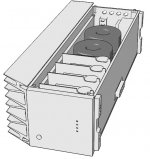
Very nice housing plan. With many high current regs in there, semis have a Tc, passives have a Tc, you should expect some cold-hot drift even with stiffest Vref choices. One good thing in this reg is that its normally a negative small drift. Thus safer than an escalating Vo. Remember to show us your build when finished. People are keen for cool ideas.
Box should be finished this weekend, regulators will follow.
There will be a mirror module on other side of box with Ni-MH cells and charger for the IV ( EUVL 's SEN ).
I was actually expecting the sink to get at least warm but it's completely cool even with your regulator at full load for 2 days !!! so i guess i can put another 2 there easy.😀
There will be a mirror module on other side of box with Ni-MH cells and charger for the IV ( EUVL 's SEN ).
I was actually expecting the sink to get at least warm but it's completely cool even with your regulator at full load for 2 days !!! so i guess i can put another 2 there easy.😀
When this regulator is at full load near its CCS set limit only the first Mosfet dissipates. At low Vo levels as for digital and logical spare current settings (non hot-rod practice) they can be surprisingly bearable.
😀😀
Changed pot for a 110R 1% MRS25 resistor and the drift was halved.
after half an hour 5.35V had dropped to 5.28V and stabilized.
So clearly the trimmer is just for initial adjustment and should be replaced with a resistor for operation.
Changed pot for a 110R 1% MRS25 resistor and the drift was halved.
after half an hour 5.35V had dropped to 5.28V and stabilized.
So clearly the trimmer is just for initial adjustment and should be replaced with a resistor for operation.
Well done. I did not recommend that substitution to no effect as you saw, still the trimmer's fate is to be evaluated versus drift demand in each application by each user. SSLV1.1 PCB has a configurable Vref area to be intrinsically flexible anyway.
Tempco action on vref... quite normal in these implementations... My builds take 30 min to setle down.
First Salas
I am working on my Salas reg. I want to use it for a Logitech Touch. I believe I have built it correctly. My question is how hot can IRF9530 get? Also R206 how hot can it get? Both are running at about 260 F.
I am working on my Salas reg. I want to use it for a Logitech Touch. I believe I have built it correctly. My question is how hot can IRF9530 get? Also R206 how hot can it get? Both are running at about 260 F.
That is 126C. Too hot especially for the semi. Are you using a contact thermocouple to read the temp?
In what room temp, CCS setting, load dummy? Are you aiming the black part of the semi's case from about 15cm (half foot) distance?
Room temp. is about 80. I have just shy of 1 amp that I am shooting for. I grabbed a thermocouple and am checking with that now. It is showing 188 F.
Thermo is now showing about 200 F. I use it for roating coffee so I am not sure it is accurate in this situation as it is .188 in diameter. Infared is still showing about 260-270 F.
Yes it is about a half a foot. It was doing it with dummy load. Which was 5R5. I have since hooked it up. I have now unplugged it seeing as how you say that is too hot.
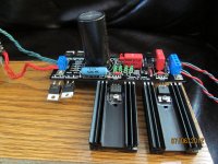
Best case 188F=87C. Junction to case is 1.7C/W in that semi (IR datasheet), so you are at 100C junction temp for say 5W. (Meltdown @ usually around 175C). Either you got a very small sink for that setting, or you are using a dummy load that isn't simulating as strong current draw as the destination load's average and too much is burned on the Mosfet. Your voltage setting and dummy load value please? Also some info about your sink (C/W) or photo?
Voltage setting is 5 volts.
 Not sure how to upload picture. When I had a dummy load hooked up it was 5r5 15 watt
Go Advanced under reply messages, there is upload pics menu. Make it say 1024X768 first.
Something here does not compute. If you got 1A CCS setting and a 5.5R dummy, then 0.9A should have gone to the dummy @ 5V. The output Mosfet should dissipate only 0.1A*5V=0.5W. But yours is suspiciously hot. Maybe you run much higher CCS? You will know by voltage across the CCS setting resistor divided by its value. Is the dummy hot at all?
Something here does not compute. If you got 1A CCS setting and a 5.5R dummy, then 0.9A should have gone to the dummy @ 5V. The output Mosfet should dissipate only 0.1A*5V=0.5W. But yours is suspiciously hot. Maybe you run much higher CCS? You will know by voltage across the CCS setting resistor divided by its value. Is the dummy hot at all?
- Home
- Amplifiers
- Power Supplies
- SSLV1.1 builds & fairy tales