Those sinks are quite minimal by the way.
Yes, I put them on for testing. They will sink to chassis floor in the completed build.
The PS seems to be quite happy chugging along at 24Vdc at the output. My input voltage is 23Vac with the load on it, this would give me ~32Vdc at the regulator, correct? with the output voltage trimmed to 24Vdc this would give me 8V to spare in the regulator, correct? Q301 stays quite cool at 31°C, Q306 cycles between 32°C and 36°C over a period of a minute or so. Last night Q306 cycled between 39°C and 41°C. Is this normal? I noticed line voltage is up a little bit today and also that it takes about 5 minutes for the output to creep up to 24Vdc. Thank you very much for all you do Salas!

PS I'm not sure of my selections for capacitors, I just put in what I had laying around. Any suggestion? Also, I have 4.6Vdc between pins 1 and 3 on Q301.
PS I'm not sure of my selections for capacitors, I just put in what I had laying around. Any suggestion? Also, I have 4.6Vdc between pins 1 and 3 on Q301.
Last edited:
All descriptions seem normal. You should also deduct 1.4V total rectification diodes drop from expected raw DC calculations. Line voltage level can add or subtract little heat from Q301. While Q306's heat is affected by CCS setting minus load consumption in mA times Vout Voltage (producing Watt). Both are affected by ambient temperature of course. Your capacitors are very good types. What is the voltage drop across the legs of the 10R CCS resistor?
What is the voltage drop across the legs of the 10R CCS resistor?
2.6VDC
BTW this isn't going to be the actual transformer I use in this build. I can order something with more Voltage if advantageous.
Last edited:
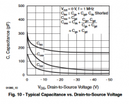
2.6V/10R = 260mA CCS. Up to 10-15V Vin-Vout (VDS) seems still logical for Q301's dissipation given your measured temp with 7V. More voltage across promotes less parasitic capacitance inside Q301. In any case never use less than 5V. It becomes quite slower (capacitive) under 5V VDS.
Attachments
If I take off power to light an LED from here,

where do I return the negative lead to the board?
where do I return the negative lead to the board?
Between the two upper left pads (anodes) and the two upper right pads (cathodes) of the unused diode positions in your photo you have zero and raw DC +. You could wire to a current limiting resistor and LED between those. LEDmA=(RawDC-Vf)/R.
There is rectification waveform there. Better avoid to introduce cables and parts right there. Not to propagate EMI.

I see what you mean. Wide Nichicon reservoirs block access. No worries, find with the beeper the corresponding legs of the TO-220 diodes to those pads and wire from there.
If their legs are too short lift the board and wire a twisted pair feed from the reservoir +/- legs. +V to limiting resistor, from there to LED's anode, cathode to -V return.
For 27VDC output, what configuration do you recommend? It will power cascode 2SK170BL MM phono stage. Power consumption for both channels MAX 30mA.
I have 24VAC transformer, about 30VA.
Regards
I have 24VAC transformer, about 30VA.
Regards
For 27V rail on common between channels PSU you may set 130mA CCS. Resulting to 2.7W Q106 dissipation for 30mA load consumption and 100mA shunt current. Very manageable.
On how to configure the reg best for the target CCS current and the voltage range of interest, both the XLS calculator and the PDF manual from post#1 have all the details.
On how to configure the reg best for the target CCS current and the voltage range of interest, both the XLS calculator and the PDF manual from post#1 have all the details.
What voltage ref. for 6.3V, I want to try for filaments?
Better to know for Vout between 5 & 10V
Better to know for Vout between 5 & 10V
Last edited:
Salas I don't have 2K trimmer on hand, I have 1K or 5K & fixed resistors. Now I'm just looking to set for 6.3Vout 1A
Last edited:
- Home
- Amplifiers
- Power Supplies
- SSLV1.1 builds & fairy tales