Too heavy a dummy load. Should be drawing half your CCS to 3/4 is correct. Use a 15R 2W-5W dummy to emulate ~220mA draw, set for 350ma to 450mA CCS. Check voltage drop across R301 to estimate what current you have available to use.
15R 5W dummy load
Vout +1.52V still can't adjust Vout with the trimmer
Voltage across R301 12R (+1.22V)
Vout +1.52V still can't adjust Vout with the trimmer
Voltage across R301 12R (+1.22V)
R301 2R7 (voltage across 0.81V = 300mA)
Vout 3.3V🙂
Now YES: trimmer adjust Vout & all LEDs lit strong
Time to compare vs Trident TP stuff
Vout 3.3V🙂
Now YES: trimmer adjust Vout & all LEDs lit strong
Time to compare vs Trident TP stuff
You will have to know what the circuit draws without Tridents since you are about to check without them. I have read that a Buff 2 draws 410mA with Tridents on it. Anyway, keep in mind to have whatever it needs in the end +100mA in CCS reserve. If it takes 200mA for instance, you are OK with 300mA.
I lowered R301 till 2R2 so now I have 330mA, I will do the comparison vs the Trident clock regulator
I am not Russ to surely tell you what consumes how much in those modules, but I trust you will make it out in practice. Its shown that your reg works when the currents are at correct proportions, that's enough to start. Good luck.

The BII it's with Salas V1.2R + BiB for the clock, now it's time to change the other 3.3V Trident, wich voltage & current needs the AVCC?
Normally 3.3V, but the AVCC throws about 3.5V to achieve better dynamic range. Not shure about the current, but i guess it would be a few mA. I was thinking that the most significant sonic influence would be on the analog supply. That' s why the stock Buffalo II had shunt regs is this position from the beginning.
I don't know about analog side but clean regulated DC for clock it's a big difference between Trident or Lifepo vs BiB
The BII it's with Salas V1.2R + BiB for the clock, now it's time to change the other 3.3V Trident, wich voltage & current needs the AVCC?
It's linked to your clock frequency. It about 36mA under 3.3v @ 50mhz and should be about 55mA 3.3v @100Mhz
100~150mA shunt reg should be Ok
...quad of green LED's rather than triplet in CCS...
Whoa, that woke it up. E/R=I, 3.25V across R1, R1=5.6 ohms.... 580mA. Dummy load is 12.6 ohms, output set at 5.3V = 420mA to simulate Buffalo 2 w/ Trident regs. (DC Vin is 11.3V, 6V headroom)
One of my CCS LED's glows a bit yellow, anything I should be concerned about? My 5W Vishay's should be here in a couple of days so I'll try those out before any more "quad mods". But, an interesting experiment, and would certainly power my DAC at this point for a test.
What can I do with you Buffalo guys all over, I talked to Crt for adding a 4rth one in the next run for your convenience.😀 They can be red also, to keep the voltage diff a bit tamer. Near 2W burning constantly on your 5.6R, now... Will make a 5W spec very hot in practice. Keep it off PCB distant enough.
Better change it.
One of my CCS LED's glows a bit yellow, anything I should be concerned about?
Better change it.
Normally 3.3V, but the AVCC throws about 3.5V to achieve better dynamic range. Not shure about the current, but i guess it would be a few mA. I was thinking that the most significant sonic influence would be on the analog supply. That' s why the stock Buffalo II had shunt regs is this position from the beginning.
It's linked to your clock frequency. It about 36mA under 3.3v @ 50mhz and should be about 55mA 3.3v @100Mhz
100~150mA shunt reg should be Ok
Thank you guys🙂
Well, new current set resistors are in. Good and bad news. Legato supply current is almost exactly where I want it. Positive side is +14.9V@334mA (Rset=5r). Negative side is -13.9V@296mA (Rset=3.3r). These rail voltages put my Legato in the "sweet spot" (VCC/2)-1V . It all looks quite sinister on my chassis, Darth Vader would probably use these regs in his projects. Tried a 2r for Buffalo supply (5.3V), ....runs 650mA, so I plan to back that off. Probably needs about a 2.5r I would guess.
Can't comment on the sound quality because I've done something to the right channel on my Legato, no fault of the supply itself. I won't go into it because this is the BiB thread. I'll try to get it sorted out next week. My solder rework equipment at my workplace far exceeds what I have at home.
Can't comment on the sound quality because I've done something to the right channel on my Legato, no fault of the supply itself. I won't go into it because this is the BiB thread. I'll try to get it sorted out next week. My solder rework equipment at my workplace far exceeds what I have at home.
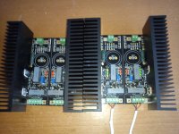
Just for fun
One pic with new heatsinks mounted, just for fun. Will be nice to have R101, 201 & 301 with a small space to fit Caddock or other precision power resistors also can be sinked to the heatsink.
One pic with new heatsinks mounted, just for fun. Will be nice to have R101, 201 & 301 with a small space to fit Caddock or other precision power resistors also can be sinked to the heatsink.
Attachments
Last edited:
- Home
- Amplifiers
- Power Supplies
- SSLV1.1 builds & fairy tales