Right now Parts Connection have a 20% off almost everything including vacuum tubes.
They usually have this offer twice per year. These are the times when I get my
vacuum tubes from them. I have purchased several times over the past few years.
The odd thing is that when you first build your shopping list, the discount isn't shown. On the other hand, when they send you the complete invoice, together with shipping, the discount does show up.
I should have most of the parts tomorrow and then I'll just need another small order from Digikey.
Sorry to hear. I find it highly disturbing that companies put people on the street after 41 years of service... I am wondering how the responsible management can sleep at night.....
Just my 2cents
Yep, shame on them not recognising talent. It seems to me there's no respect for qualified personnel in Northern America.
Checkout process and chassis questions.
I am thinking of re-using an old organ switch for powering on the SSE. Is there a way to safely test this with the IEC + Fuse arrangement? Also, when doing the checkout process, or initial testing, I have read that some people use a normal lamp to test their circuits. What would be the safest way to check it on power up, without damaging the transformers and the tubes?
I already have drilled the holes for the IEC plug as well as the Fuse socket, craftsmanship not up to par, so I'll probably need to fill in the irregularities in the pine surface. No idea how to do that yet until there's some pine-looking filling material I could get at the store.
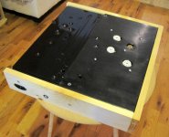
I noticed something while wet sanding the black chassis: of course, the surface does become quite flat and smooth to the touch. However, the black paint becomes greyish.
I am not sure whether I am scraping off too much (doesn't seem like it since I use 800 grit with a sponge, then 1,000 and do not scrub too much after several coats of black paint) and hitting the grey primer underneath, or it's the effect of compacting the black paint granules on the surface(?).
In the end, I want this to have a black glossy look, but until now I only manage a black-grey/striped look... 🙁
So, I am probably going to end up just putting in several coats of black and leave it at that if I cannot do it better, but of course, it won't look polished.
I am thinking of re-using an old organ switch for powering on the SSE. Is there a way to safely test this with the IEC + Fuse arrangement? Also, when doing the checkout process, or initial testing, I have read that some people use a normal lamp to test their circuits. What would be the safest way to check it on power up, without damaging the transformers and the tubes?
I already have drilled the holes for the IEC plug as well as the Fuse socket, craftsmanship not up to par, so I'll probably need to fill in the irregularities in the pine surface. No idea how to do that yet until there's some pine-looking filling material I could get at the store.
I noticed something while wet sanding the black chassis: of course, the surface does become quite flat and smooth to the touch. However, the black paint becomes greyish.
I am not sure whether I am scraping off too much (doesn't seem like it since I use 800 grit with a sponge, then 1,000 and do not scrub too much after several coats of black paint) and hitting the grey primer underneath, or it's the effect of compacting the black paint granules on the surface(?).
In the end, I want this to have a black glossy look, but until now I only manage a black-grey/striped look... 🙁
So, I am probably going to end up just putting in several coats of black and leave it at that if I cannot do it better, but of course, it won't look polished.

'Toobs, We Got Toobs'
Did you get any spares ? It's good to have some spares on hand, at least a
spare rectifier.
Did you get any spares ? It's good to have some spares on hand, at least a
spare rectifier.
'Toobs, We Got Toobs'
Did you get any spares ? It's good to have some spares on hand, at least a
spare rectifier.
The Sovtek 5AR4 is a pretty decent tube should last a good long while with this amp. (the JJ versions not so much).
Cheers,
Bob
Sockets and Solen cap...
After soldering the sockets and coupling caps, I found out one of the octal sockets was badly placed...
Now, even George says that it's near impossible to remove one without either damaging the socket or the PCB.
It took me a good half hour of painstakingly removing excess solder, heating the end of the pins and pushing the pins out, pushing them towards the centre or making a slight lever effect with the PCB and socket to be able to extract it. (I have a fair amount of experience manually extracting components from old machines to fill my salvage box - these hours came in handy).
So, I managed to remove it and solder it the right way this time, but on doing that I noticed I had burned one of the terminals slightly (no big issue here), but more worrying, I had burned off a little part of one of the Solen cap sheath.
I just hope this will still work. Well, if not I'll have to get another one and fortunately it is affordable.
PCB and wood frame pics.
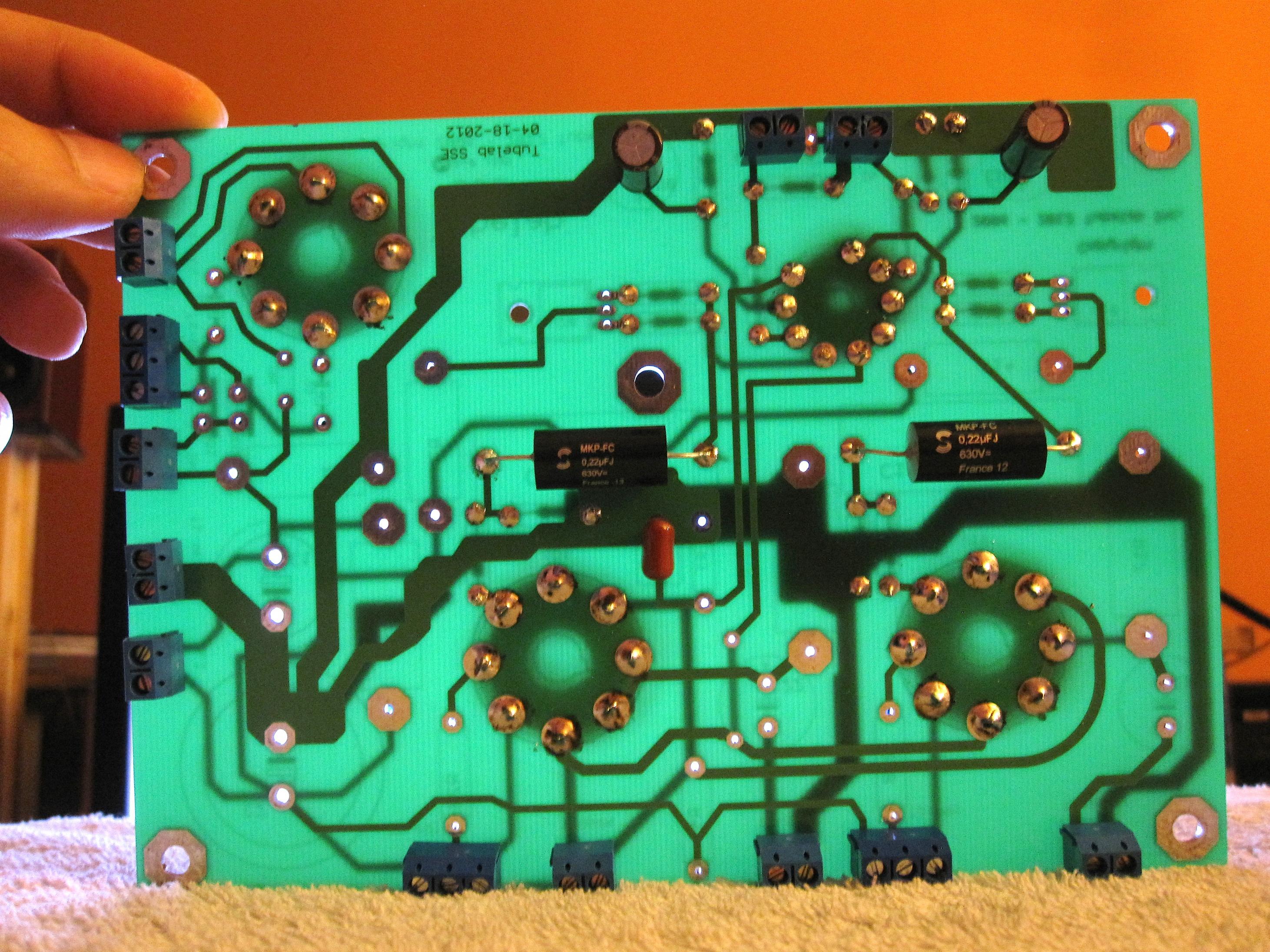
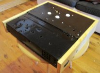
PCB partly filled, with the costly mistake with the badly placed socket on the upper right. Fortunately, I managed to extract it without damaging it or the PCB, but the corresponding Solen cap suffered a little:
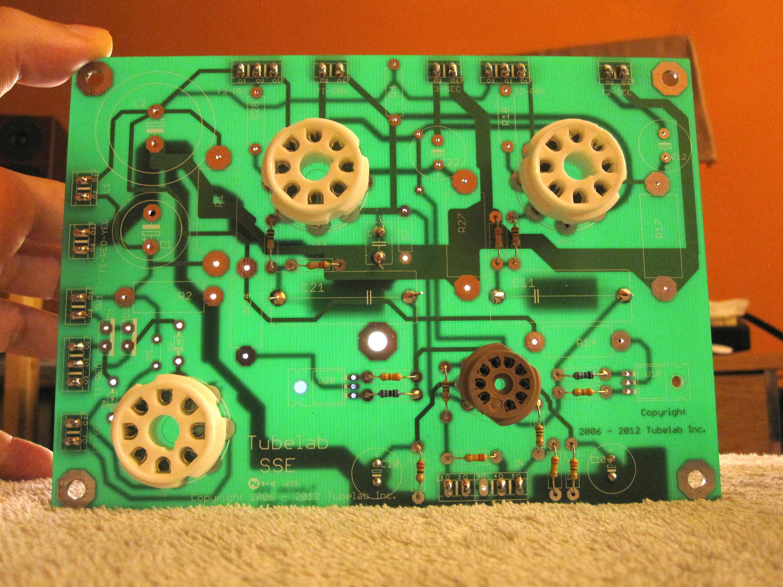
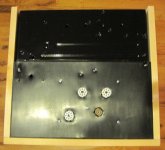
PCB with Solen caps (before sheath damage):
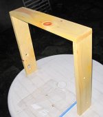
White pine frame with a couple of coating of linseed oil, drying in the garden (with IEC and fuse holes):

PCB partly filled, with the costly mistake with the badly placed socket on the upper right. Fortunately, I managed to extract it without damaging it or the PCB, but the corresponding Solen cap suffered a little:
PCB with Solen caps (before sheath damage):
White pine frame with a couple of coating of linseed oil, drying in the garden (with IEC and fuse holes):
Attachments
Looks like I have all the parts for a complete build today. I do not yet have a supplemental motor run cap, no volume knob, and some questions have been left unanswered, but I may get back to them.
After another wet sanding round yesterday, it appears the grayish look is because of scratches. This suggests that I should sand with even finer grit (2000). I tried polishing with Turtle Wax Rx polishing compound but found no difference.
The end result is a gray matte look, far from the glossy black I am looking for.
White pine with several new coats of linseed oil looks great though.
I am now looking forward to a few things:
- Completing the SSE
- Listening to great Hi-Res audio (I especially like DSD and DSD 2x and above), through the iFi iDSD Nano DAC and pre-amp into the SSE and then into the Totem Mites.
- Improving on my basic SSE setup
- Integrating a micro-processor and a touch-screen LCD screen with the tube amp for tube testing, monitoring, + other cool stuff.
Last edited:
Looks like I have all the parts for a complete build today. I do not yet have a supplemental motor run cap, no volume knob, and some questions have been left unanswered, but I may get back to them.
Get a good volume pot - a motor run capacitor - good to GREAT coupling caps
Yer well on your way to:
"- Improving on my basic SSE setup"
What part of Canada eh?
Cheers,
Bob
Hey Bob, what's up? I'm in Eastern, in Montreal.
PCB filled up.
I see D3 and D4 on the PCB as well as TR1. I am not sure I've seen any reference of those anywhere else.
[Edit] A quick search brought me to this: http://www.diyaudio.com/forums/tubelab/216689-starting-sse-build.html
Ok, I'll see if I have those and add them or else I'll just add a jumper as George suggests in an older thread.
Last edited:
I have two CL-90, so no CL-140, and I might use one on the PCB according to the instructions by rknize, unless I just jumper everything and keep the inrush current limiters for the transformers only:
Quote:
Originally Posted by rock12
on the new boards where thermisitor cl-140 goes I was going to substitute a cl-90 since I have one. For some reason these holes are smaller and the cl-90 will not fit. I would like to avoid any more shipping fees if possible thoughts?
The CL-90 is a higher-current part, so the leads are larger. Personally, I would mount it off-board rather then try to shove it into the PCB. It would go in series between the center tap of the HT winding and the PCB. It's not the ideal rating for this position, though, because it will not get not enough. It is better off in series with the entire amp. That said, I had a CL-90 in this position originally and I coped with the problem by wrapping the part in heat shrink tubing to let it get up to temp.
Get a good volume pot - a motor run capacitor - good to GREAT coupling caps
Maybe one day when budget allows. For today: no volume pot, no motor run cap, and affordable Solen caps.
I think I may have some stereo pots but they're only 10K.
D3 & D4 are the diodes that will protect the rectifier tube. If you aren't using the tube then jumper, else I'd highly suggest using them with the rectifier tube. This mod was to address the new production rectifier tubes that were arcing over, this is a safety feature added in. I've been using diodes like this with all my tube builds after one of my scratch built amps caught fire in a rectifier arc over due to hot starting the amp.
Cheers,
Bob
Cheers,
Bob
Hi Bob,
I jumpered them as I think there were some particular batches of tubes that were problematic but hopefully mine isn't affected.
I have been looking for a detailed checkout process for the SSE, but couldn't find it. There's a detailed one for the SE on tubelab.com but nothing as detailed for the SSE.
[Edit: added links to checkout info, as the diyaudio search this morning gives better results than Google from the iPad in bed last night]:
http://www.diyaudio.com/forums/tubelab/158719-simple-se-checkout-dummies.html
http://s69.photobucket.com/user/Ty_Bower/media/Simple%20SE/Checkout/ohm00.jpg.html
Yesterday, as I was preparing to screw in the transformers, I noticed that some of the fixing holes weren't large enough for the screws that I have, so I still need some additional mechanical work today before I can hope to assemble for wiring.
So far, this is what I did yesterday:
1. Completed the PCB, used salvaged heat-sinks. Mounted the heat-sinks so that they hover underneath the PCB, fins parallel to the board, but not touching the board. I think I will have the fins line vertically instead for better convection. Jumpered D3, D4 and the inrush pads.
2. The PCB has been mounted with spacers (cut for proper adjustment from existing synth PCB spacers) to make the upper surface of the sockets flush with the upper chassis.
3. Screwed the IEC socket in the wood frame after drilling the mounting screw holes with the Dremel.
4. Bolted the fuse holder into the wooden frame with a gripping washer and a nut.
5. Read up on transformer placement and induction. It seems my placement is okay, although I would probably have preferred a larger distance between the two Output transformers.
6. Refreshed my memory on safety.
7. Looked for checkout process details. Found some snippets of info in a post somewhere, but nowhere as detailed as in the SE checkout page. Maybe there was a more detailed page on the previous website incarnation I think.
8. Removed transformer stickers on the bells and sides, keeping the transformer wiring and characteristic info sticker below (invisible in my build).
When I adjust the mounting holes today, I will also verify the input and speaker holes as I want to be done with the mechanical/heavy machinery work to get back to the electrical and electronic work which is more fun to me.
I thought of a few things too, but I am not sure if I will proceed immediately with them:
a. Painting the laminations of the transformers in glossy black.
b. Re-orienting heat-sink fins.
c. Adding some rubber spacers beneath the transformers at screw mounting holes.
d. Adding wood corner bracing. I will have to do this at some point.
e. Adding 2cm feet. I definitely will do this later.
f. Adding convection holes around the tube socket holes as I wonder if there's enough air-flow as the chassis is currently.
Last edited:
Wiring and grounding question
Installed the transformers today. The amp is very heavy with them, so I ended up working a lot upside-down today for wiring.
Wiring the Power transformer was easy as detailed on the website but transposing with the Edcor description of the OPT wires and making sure the proper Centre-tap is used. For the OPT, I had to search and found an answer by... Bob. So I know that the Edcor OPT 8ohms goes to + for the speaker.
However I am stumped about 'grounding the speaker terminals'. I have a tab on it, but there does not seem to be a separation from the signal to this tab. So I thought that the OPT wires should be soldered to that tab, but then what would be the ground?
Here are some pictures.
Wiring (can someone please double-check the component on the heat-sink on the right (the label is right-facing on this picture, to verify if it's well-oriented? Thanks):
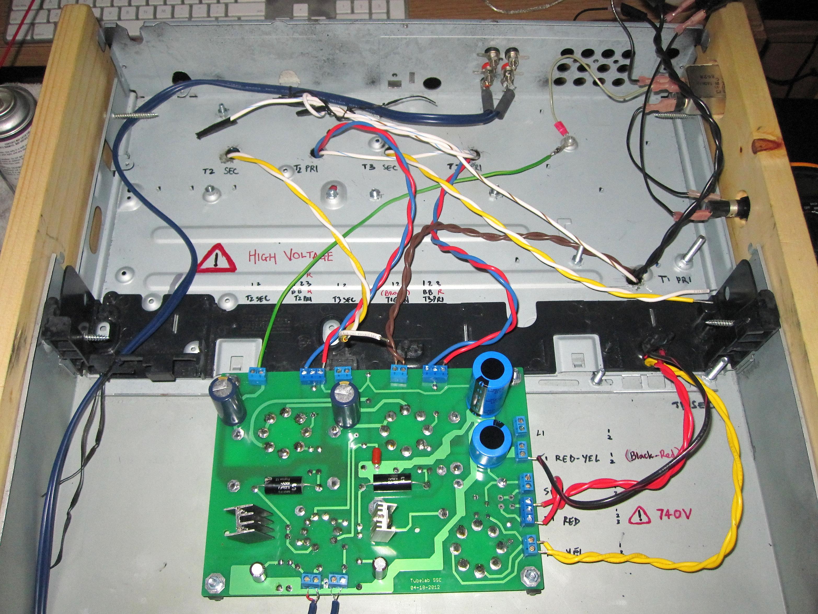
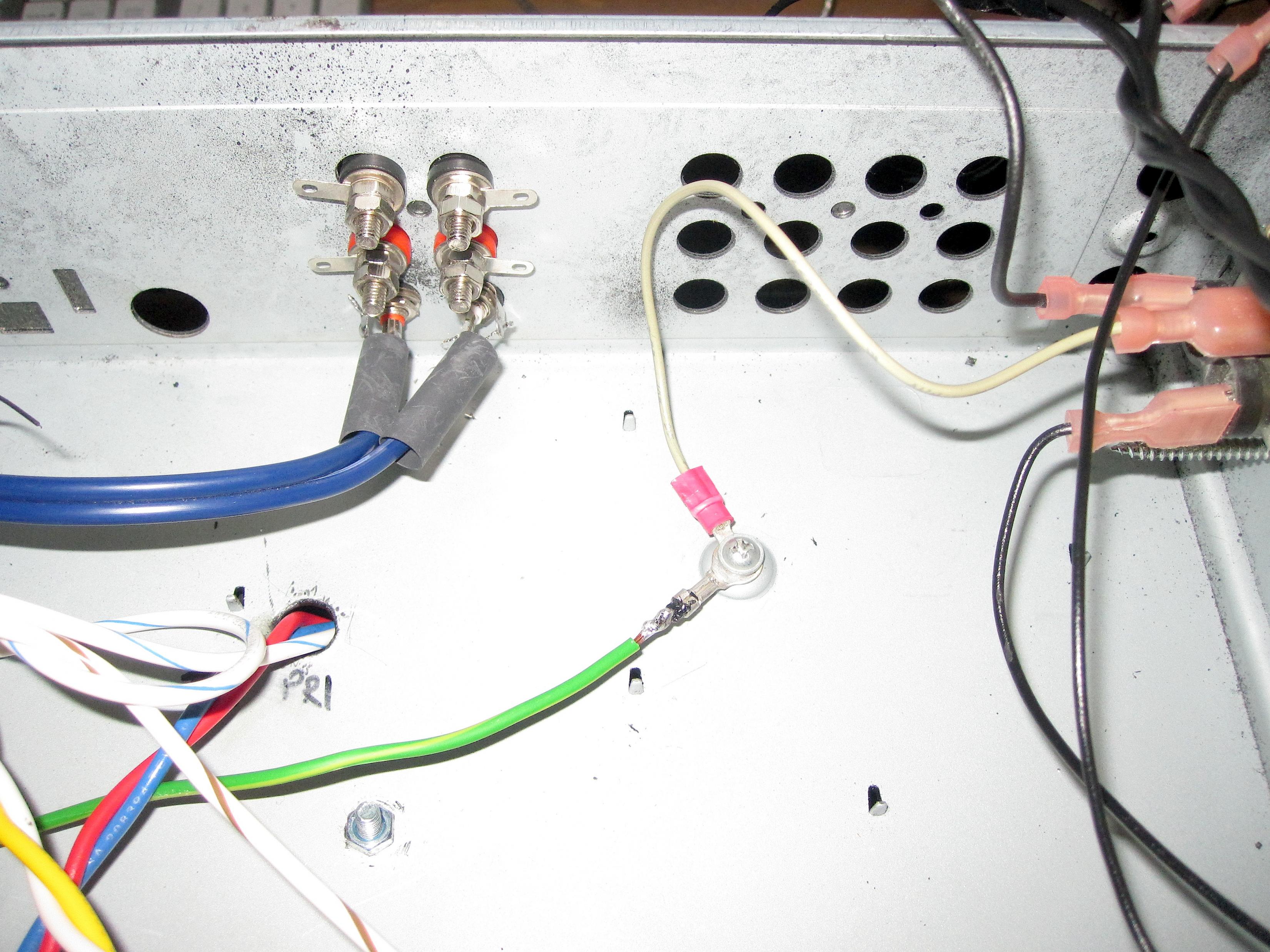
Speaker terminals (no idea how to ground and connect this to the wires as the central shaft is connected to everything including to what looks like a ground tab that you can see horizontal):
Installed the transformers today. The amp is very heavy with them, so I ended up working a lot upside-down today for wiring.
Wiring the Power transformer was easy as detailed on the website but transposing with the Edcor description of the OPT wires and making sure the proper Centre-tap is used. For the OPT, I had to search and found an answer by... Bob. So I know that the Edcor OPT 8ohms goes to + for the speaker.
However I am stumped about 'grounding the speaker terminals'. I have a tab on it, but there does not seem to be a separation from the signal to this tab. So I thought that the OPT wires should be soldered to that tab, but then what would be the ground?
Here are some pictures.
Wiring (can someone please double-check the component on the heat-sink on the right (the label is right-facing on this picture, to verify if it's well-oriented? Thanks):
Speaker terminals (no idea how to ground and connect this to the wires as the central shaft is connected to everything including to what looks like a ground tab that you can see horizontal):
Attachments
Last edited:
Ok, got it: speaker -ve will be grounded, and I also need to add a couple of jumpers at the terminals and I should be ready for preliminary testing.
- Home
- More Vendors...
- Tubelab
- SSE first build, caps and other questions.