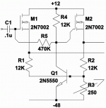
Here is my half-baked silicon version of the tube circuit in my earlier post. My design effort consisted of replacing the tubes with MOSFETS, adding bias and gate resistors and taking a few educated (or wild depending on your point of view) guesses on values.
Under simulation it provides just over 20Vpp into a 100kohm load. However, it does not appear to be stable. A compensation capacitor (or two) is needed, but I haven't looked into that yet.
Disclaimer: If anybody is fool enough to actually build this thing, make sure a fire extinguisher is within reach and stand well back before turning it on!
Attachments
Here is my half-baked silicon version of the tube circuit in my earlier post. My design effort consisted of replacing the tubes with MOSFETS, adding bias and gate resistors and taking a few educated (or wild depending on your point of view) guesses on values.
Under simulation it provides just over 20Vpp into a 100kohm load. However, it does not appear to be stable. A compensation capacitor (or two) is needed, but I haven't looked into that yet.
Disclaimer: If anybody is fool enough to actually build this thing, make sure a fire extinguisher is within reach and stand well back before turning it on!
While it's an over simplification, think tubes for voltage amplification and FETs for current amplification. NOTHING ELSE is as linear as the vacuum triode. If you are determined to use FETs for voltage amplification, use cascoded pairs and shield that which is upstream from a potentially varying CMiller.
A mosfet with resistors above and below, driving a resistive impedance
would be extremely linear at DC. As there's nowhere else a DC current
can go, the voltage gain relationship of the resistors is fixed. This could
very well equal the voltage gain linearity of a triode in the same circuit.
Now you do have a non-linear capacitance that squirms back and forth
with the drain bias. AC might not obey the resistor rule where there is
opprtunity to ditch the straight path, hide in a wiggly cap, and return
at some later inconvenience. But as you point out cascodes....
I've been wanting to try a MOSFET concertina splitter for some time. I have done a successful amp that used a jfet differential input stage cascoded on each side with 1/2 of a 6CS7 (the small half, if I remember correctly). The second, beefier halves were pressed into service as a cathode followers to directly drive the output tubes, allowing modest dips into A2 operation. The circuit is shown in the "Kingfisher" thread at http://www.diyaudio.com/forums/tube...amp-using-7591a-outputs-fisher-500b-iron.html .
Last edited:
how much does tube wear influence the balance ?
when does it happen
and could that make the SS splitter a good option
when does it happen
and could that make the SS splitter a good option
If we speak of concertina, I doubt wear affects balance.
Would likely work as intended, till it died completely.
Fact you can throw sand in there, and doesn't change
anything, should in reverse thinking tell you why wear
also changes nothing, or very little.
The unity gain topology provides tons of local feedback.
Till your device's gM*R type gain degrades less than 1,
the excess will be strongly corrected by local feedback.
Mu (or sandy lack of Mu) is not a significant player here.
Last edited:

Use Mu where it counts, voltage gain. Use sand where gm is king.
If concertina is sand (a stage with with no voltage gain of its own),
then your small twin triode is made available for TWO gain stages...
Refer to #13 for practical example. Just one 12AX7 in hybrid,
drives 6L6's with similar open loop triode gain as full Williamson
that requires a whole extra differential stage after the concertina.
And an entire unnecessary pole of phase shift is eliminated.
Last edited:
Use Mu where it counts, voltage gain. Use sand where gm is king.
If concertina is sand (a stage with with no voltage gain of its own),
then your small twin triode is made available for TWO gain stages...
Refer to #13 for practical example. Just one 12AX7 in hybrid,
drives 6L6's with similar open loop gain as full Williamson that
requires a whole extra differential stage after the concertina...
i like this, makes a lot of sense to me.😀
Originally Posted by kenpeter View Post
Use Mu where it counts, voltage gain. Use sand where gm is king.
If concertina is sand (a stage with with no voltage gain of its own),
then your small twin triode is made available for TWO gain stages...
Refer to #13 for practical example. Just one 12AX7 in hybrid,
drives 6L6's with similar open loop gain as full Williamson that
requires a whole extra differential stage after the concertina...
i like this, makes a lot of sense to me.
CCS load the 1st gain block, to push gain and linearity up. "Horizontal" load lines are "sweet". Use an unbypassed cathode resistor for bias and isolate the stage from the NFB loop. Local current NFB takes care of linearization. Cap. couple the 1st gain block to the 2nd gain block. DC couple the 2nd gain block to the MOSFET "concertina" phase splitter. The "Boogeyman" of low freq. instability is buried. 😉 Only 1 high pass pole is inside the NFB loop; it's between the splitter and "finals".
BTW, an 'X7 section in the 1st gain block and a 'T7 section in the 2nd gain block seems correct to me. Get something with substantial gm inside the NFB loop and obtain some protection against HF error correction signal induced slew limiting. Another advantage of the 'T7 triode is its ability to drive a modest load. A big MOSFET, like the IRFBC20, is fine for the "concertina". I am not comfortable with the WIMPY 'X7 triode driving any MOSFET other than the ZVN0545A.
Last edited:
The "gm is king" concept was one of the reasons that I used jfets cascoded with triodes as a differential front end/phase splitter for a P-P tube amplifier, as well as the relative ease of matching sand-state devices. I took that concept to an extreme in a subsequent design where I ditched the triodes and used jfets cascoded with bjts as the front end of another amplifier design - that one's sitting in the basement waiting for me to finish it one of these days. My current interest is a folded cascode differential front end with no coupling caps between input stage and output other than the one I always insist on having between the input and the cold, cruel, uncertain world outside the amplifier.
Last edited:
It's worth a try if you can find one shall enough. For a solid state splitter, I would tend to use as small a device as I can (paying close attention to power dissipation), in order to reduce the capacitive loading of the previous stage as much as possible.
The 2 MOSFETS I favor are the ZVN0545A and the IRFBC20. Both parts exhibit a small and "stable" reverse transfer capacitance, which is the crucial specification for a FET serving as a voltage follower or "concertina" splitter.
The capacitances of the ZVN0545A are small enough that WIMPY high RP/low gm triodes, like those in the 12AX7/ECC83, drive the FET with great aplomb.
Experience indicates that a protective Zener diode be installed between gate and source, to protect against power on time trouble. Remember, we DC couple the FETs to the preceding tube's anode.
 thanks for the good tip
CCS load the 1st gain block, to push gain and linearity up. "Horizontal" load lines are "sweet". Use an unbypassed cathode resistor for bias and isolate the stage from the NFB loop. Local current NFB takes care of linearization. Cap. couple the 1st gain block to the 2nd gain block. DC couple the 2nd gain block to the MOSFET "concertina" phase splitter. The "Boogeyman" of low freq. instability is buried. 😉 Only 1 high pass pole is inside the NFB loop; it's between the splitter and "finals".
BTW, an 'X7 section in the 1st gain block and a 'T7 section in the 2nd gain block seems correct to me. Get something with substantial gm inside the NFB loop and obtain some protection against HF error correction signal induced slew limiting. Another advantage of the 'T7 triode is its ability to drive a modest load. A big MOSFET, like the IRFBC20, is fine for the "concertina". I am not comfortable with the WIMPY 'X7 triode driving any MOSFET other than the ZVN0545A.
X7 isn't driving any mosfet without help, PNP sand is boosting gm.
And gain of that hybrid splitter stage is only 1/2 Mu each end...
You can route GNF back to the 2nd stage and cut another cap out
of the loop. But then split impedances may not balance anymore.
You would have to be careful not to upset (R1+R2)/R1=Mu.
If you roll an AT7, you would need to adjust accordingly.
Any disturbance on the cathode collector end (from GNF) should
copy to the emitter plate side (and invert) due to the impedance
equalizer. And this works in reverse too, if you wanted to put GNF
back to the topside instead. I was only thinking of this in terms
of being a PSRR problem. But maybe could be a useful feature.
Maybe inject some ripple to cancel some ripple? Put on my tinfoil
hat and try to channel some Broskie...
If you plan to cut 100X or more out of the open loop, don't expect
much help from GNF for linearizing beam tetrodes, caps, and iron.
Probably also detrimental to PSRR...
Last edited:
- Status
- Not open for further replies.
- Home
- Amplifiers
- Tubes / Valves
- SS phase splitters?