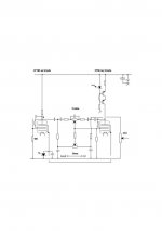
Here was the basic idea which started a bunch of successful off-springs:
*facepalm*
IOW it's NOT a CCS.
I don't mean the servo, that's fine. I mean the R shunting directly across it.
Tim
*facepalm*
IOW it's NOT a CCS.
I don't mean the servo, that's fine. I mean the R shunting directly across it.
No CCS have an infinite dynamic resistance. As well as no load has one. The whole engineering thing is about right optimization.
R actually is not shunting; it is sensing.
Some basics for the less experienced.
Take a look at a triode characteristics graph which shows gm, rp and mu as a function of anode current. You will see that mu is reasonably stable with changes in anode current but rp and gm change significantly with anode current.
To generate a signal voltage at the anode you must swing current through the anode load (either a resistive load or a CCS). This same current flows through the triode. As the current through the triode changes (with signal) so does it's rp - its internal dynamic resistance. It is this changing rp which is the inherent source of the harmonic distortion - write it on the back of you hand and remember it.
DELTA rp IS THE SOURCE THE HARMONIC DISTORTION.
The amount of distortion is a function of the ratio of load impedance vs the tube rp change.
For a given level of output voltage at the anode a higher load impedance infers a lower signal current swing (to achieve that same signal level) and hence a lower rp change. You can only take that load impedance so high using a resistor for the anode load. BUT with a CCS you can get a much higher AC impedance => much lower tube current swing => much lower rp change => much lower distortion.
You can see by this that (from a distortion point of view) the "measure" of a CCS "goodness" is its AC impedance.
Of course - if the load from the following stage is too low an impedance ( this is effectively in parallel with the anode load resistor or CCS) it won't matter how high an impedance the anode load is, as the signal current swing is then determined by the next stage input impedance and then a CCS anode load won't do much for you. In that case reducing distortion requires increasing the impedance presented by that next stage.
Guitar Amp guys make use of this to deliberately get some distortion - A 12AX7 stage with a 100K Anode load is often seen driving 220K input impedance of the next stage. For HiFi that is just plain bad design - for a guitar amp it is just what we want.
Hope this is of some benefit to the "learners" here. There are other secondary contributors to distortion but what is described here is the main source.
Cheers,
Ian
Does anybody have measurements results for SS CCS?
Oh yes I have. Despite all the unscientific claims that it adds upper end thd; not in my case. The opposite. The only caveat; I am using pentodes config as triodes so the effective impedance is reduced when compared to the high Ra of the pentode. So the problematic hidden capacitance of the CCS pass driver is masked to insignifigance when using it for equivalent lowish impedance circuits.
Theme read:-Morgan Jones, book page 138 ++ Valve amps 3rd ed.
Study the fft spectrum. Gen carrier set 0dB 2.5V rms # 1Khz; F2 sits notch under -80dB and F3 more under. I couldn't ask for more.
The circuit was a Baxandal tone control using pentodes as a triode. This is the perfect application for a CCS in the anode.
Sometime ago I've tried a CCS for the anode load on a pentode video tube and it gracefully oscillated, (damned obvious, thinking about it, that a tube with such a fantastic Ft with unlimitless anode impedance will bound to oscillate) a bad move as I did the check on an unscreened pentode so CCS on pentodes is not a wise thing, even with a tight layout. The damping from the anode resistor has gone to near infinity, all what remains is the internal electrode capacitance (often a mere 0.2pF) and the several pF of the hidden CCS pass transistor capacitance + layout leads opening up possibilities of instability. So there is a worstcase point that even if a design worked, the CCS would act as a capacitive shunt, increasing thd.
As always I'm open on my theory but I'm avoiding pentodes. My cellar comes first.
richy
Attachments
Hello guys
I always find that the best ccs load is an inductive load.
What do you think?
With a low rp tube you can get away with quite a manageable choke.
I can say that the iron on top of some low rp linear tubes to be sonic revelation
I always find that the best ccs load is an inductive load.
What do you think?
With a low rp tube you can get away with quite a manageable choke.
I can say that the iron on top of some low rp linear tubes to be sonic revelation
The reason he thought this is probably because often a circuit will sound harsher with the SS CCS.A person I know with many years experience of designing and building tube amps told me that Solid State CCS, especially in the anode circuit, add high order harmonic distortion
That is what many many many listeners have found. But the conclusion that that is because of increased high-order (or odd-order) distortion is AFAIK unfounded.
What the reason is I can only speculate about. But possibly...
The first is that 2nd order harmonics are lowered which makes the higher order distortions more audible. Leading the listener to conclude that his circuit distorts more. While in fact THD is down. But THD is irrelevant or virtually irrelevant. However according to Pete Millet his one test with a SS CCS he found NO increased higher order distortion:
From: Current SourceFrom these tests, it looks to me like the Ixys part performed well. Compared to the resistive-loaded stage, both at low and high output levels it lowered the distortion quite a lot, and didn't introduce any odd-order harmonics anywhere that I could see
The only downside he found was:
is that clipping can be more abrupt than with an all-tube system. But right up to clipping, the distortion was all typical SE tube, 2nd harmonic distortion.
Gary Pimm theorizes that the shunt capacitance of a CCS is very important when it comes to affecting the sound. The lower the shunt capacitance the better the sound is how I read his theory.
From: Active loads and signal current control
The reason he thought this is probably because often a circuit will sound harsher with the SS CCS.
That is what many many many listeners have found. But the conclusion that that is because of increased high-order (or odd-order) distortion is AFAIK unfounded.
Okay, my response to this; Are there any listeners who are using a CCS in the anode and claim the sound is harsh ? I would love to see such circuit arrangement.
richy
Okay, my response to this; Are there any listeners who are using a CCS in the anode and claim the sound is harsh ? I would love to see such circuit arrangement.
Not me. But I don't use high distortion tubes, and my system doesn't need the sweetening of excessive 2nd harmonic honey.
I *can* give you a circuit with a CCS anode load that will measure and sound like poopoo. But why obsess over bad circuits?
.......I should have mentioned in pre-amps only.
Yes, SY, I also use low THD tubes or close enough to, even though someone gave me piles of ECC82's to catch cold over. I hate these.
BTW; any news of MJ's new book ?
richy
Yes, SY, I also use low THD tubes or close enough to, even though someone gave me piles of ECC82's to catch cold over. I hate these.
BTW; any news of MJ's new book ?
richy
Wavebourn, what's the benefit of gyrator over CCS?
Stable anode voltage. With plain CCS it depends on tube's brand, age, and temperature of electrodes.
Choke load gives the same stable anode voltage, but Gyrator does not have core distortions and works in wider frequency band than the real choke.
BTW; any news of MJ's new book ?
Well, you could always ask him and see if he'll spill the beans. I've taken a vow of silence.😀
Choke load gives the same stable anode voltage, but Gyrator does not have core distortions and works in wider frequency band than the real choke.
That last is a very important point. The choke can have greater swing, but the HF impedance (not to mention size, cost, and potential hum pickup) is inferior to a gyrator or CCS load.
That last is a very important point. The choke can have greater swing, but the HF impedance (not to mention size, cost, and potential hum pickup) is inferior to a gyrator or CCS load.
Certainly true from my experience, even with low rp triodes only the best plate chokes will get you above 50kHz or so -3dB. If one must use a choke instead of a gyrator (or ccs) Lundahl chokes may be worth the extra money as they do seem to have moderately lower stray capacitance than most competitors due to the insulation between layers. A certain popular 100H choke when driven by a triode connected D3A (rp < 2K) barely made 60kHz (no external load) to my considerable disappointment.
Hum pick up can be a huge issue with choke loads particularly in low level stages. In all such applications I put the PSU on a separate chassis. I built an inductively equalized and choke loaded phono stage (NOT one of my designs!) for a friend with no hum or noise issues, but assuring that result took some thought.
I use vacuum tube gyrators in some of my designs that are conceptually quite similar to the solid state design Wavebourne posted and for some of the same reasons he elucidates. A gyrator of course is not constant current, and as the transconductance changes due to aging the operating point will shift. Ip will fall, but plate voltage will be constant. In the case of a CCS the plate voltage will probably creep up as the tube transconductance falls with age. In some cases where a certain guaranteed plate voltage swing is required under all conditions a gyrator or choke may be the better choice. I use them all as it suits me. I am a bit hesitant about sand in the signal path, although SY's comments on this subject are absolutely valid, just a matter of personal (and irrational) preference on my part.
What is the concern with HF bandwidth? The HF response of all of the cascaded stages in the system is the RSS of all of the -3dB HF responses of the individual stages and it doesn't take too many stages rolling off that low to discover that you no longer have a frequency response commensurate with what is considered hifi.. (For LF take the -3dB point for each stage and convert to 1/f and calculate the RSS of these values and then take the reciprocal of the result to know the -3dB point for all the cascaded stages.)
These of course work with the 1dB point as well, but not as easy to calculate.. Never mind, 😀 no one calculates these things any more do they??
Last edited:
I would be interested in making some decent two terminal CCS or gyrators but here in the UK it always seems difficult to get the parts. You seem to either need HV depletion mode fets or some other unobtainium device.
Has anyone some ideas about using BJTs (ring of two?) two terminal CCS's?
Either that or a ready supply of DN2540 fets in the UK?
Thanks in advance!
Has anyone some ideas about using BJTs (ring of two?) two terminal CCS's?
Either that or a ready supply of DN2540 fets in the UK?
Thanks in advance!
I would be interested in making some decent two terminal CCS or gyrators but here in the UK it always seems difficult to get the parts. You seem to either need HV depletion mode fets or some other unobtainium device.
Has anyone some ideas about using BJTs (ring of two?) two terminal CCS's?
Either that or a ready supply of DN2540 fets in the UK?
Thanks in advance!
😕
In my examples you could see BJT's, but no depletion mode FETs.
😕
In my examples you could see BJT's, but no depletion mode FETs.
Hi - can you point me toward some of your examples please?
Also what is the advantage of a gyrator over a CCS, and how do you choose the values in the gyrator? Thanks in advance!
Hi - can you point me toward some of your examples please?
Also what is the advantage of a gyrator over a CCS, and how do you choose the values in the gyrator? Thanks in advance!
Page number 2 in this thread. And many other threads.
http://www.diyaudio.com/forums/tubes-valves/167903-ss-ccs-distortion-2.html#post2205691
Later we answered to the questions about advantages over CCS and chokes (myself in the first post on the current page, SY, and kevinkr). Read the thread, it has already many answers! 😉
#31, #33, #34
Last edited:
That last is a very important point. The choke can have greater swing, but the HF impedance (not to mention size, cost, and potential hum pickup) is inferior to a gyrator or CCS load.
I would say that because chokes are bigger and more expensive, they are superior in terms of size and cost.🙂 On the other hand, chokes are easier for the neophyte builder to implement. If someone who has never built an amplifier but has some resources were to ask, I would more readily recommend a two-stage, transformer-coupled single-ended amp before anything else so he stands a fair chance of completing the project.
Gyrator does not have core distortions and works in wider frequency band than the real choke.
With a well-designed audio choke on a high-quality core these are moot considerations. You and SY have engineering and technical expertise that Joshua and the majority of DIY builders haven't got. I understand trying to instruct people on the exciting profession of electrical engineering, but putting down as woo-woo simpler and easier to implement solutions isn't always helpful.
John
Last edited:
all true John, but the cost of a "well designed audio choke on a high quality core" is orders of magnitude more than a simple CCS or gyrator. And that without the consideration that we in the far-flung nether-regions of the globe have to contend with - ie freighting and the other associated costs.
In short, for many of us a CCS or other electronic device IS simpler and easier to impliment than a magnetic solution
To no small extent, this forum's neophyte members lean heavily on the skills and expertise of the generous and supportive experts including those you mention. It behoves us technically inept types to have a good go at building and understanding the designs that are sprinkled about so that we learn as well and hence bug them less.
Aside from that, I'd add that it is a horses for courses argument. I note SY's new phono pre-amp employs a magnetic front end where it could well have used an electronic solution. Its not a given that a designer leans one way or the other - a good designer applies what works best within the context of the situation.
- Status
- Not open for further replies.
- Home
- Amplifiers
- Tubes / Valves
- SS CCS and distortion