more simulation
In private correspondence with Ian, he explained the following:
"On the prototype using two MOSFETs for T1,2 the article mentioned it helps to spread the heat better over the heatsink and also reduces the thermal washer temp drop so you can use a slightly smaller heatsink with that simple tip. It is not so useful on Class-AB, only Class-A where huge heat output is expensive and bulky to get away."
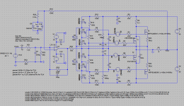
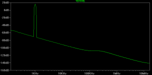
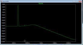
I added an opamp to the input stage, and lowered the DC offset. Simulation gives me the following performance:
THD @ 1kHz = 0.0028%
THD @ 20kHz = 0.022%
Not too bad for 50W Class-A?
How to to thermally stabilize this combination of lateral and vertical MOSFET output transistors?
dado
In private correspondence with Ian, he explained the following:
"On the prototype using two MOSFETs for T1,2 the article mentioned it helps to spread the heat better over the heatsink and also reduces the thermal washer temp drop so you can use a slightly smaller heatsink with that simple tip. It is not so useful on Class-AB, only Class-A where huge heat output is expensive and bulky to get away."
I added an opamp to the input stage, and lowered the DC offset. Simulation gives me the following performance:
THD @ 1kHz = 0.0028%
THD @ 20kHz = 0.022%
Not too bad for 50W Class-A?
Attachments
Bias & Input PCB
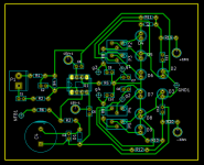
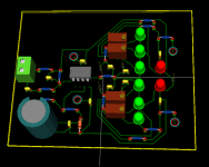
I've made my first attempt at creating a PCB for the input stage and bias circuit for Ian's Square Law Class A, as featured in Linear Audio Volume 1.
My plan is to create separate PCBs for the bias and output stages. The idea is that this will give more flexibility in mounting the output transistors to the required heatsink. This is basically the same approach that Ian took in the above mentioned article.
Attached are schematics for the entire circuit and also the input/bias module by itself. Attached are screen shots from Kicad showing the PCB for the input/bias. I will continue work on the output stage PCB.
Comments and helpful suggestions are appreciated.
Attachments
yes, lots of the heat
but poor? no hf harmonics...
chaps -- i'm digesting the more recent article but meantime - has anyone built the original 1995 version (similar to the sim here)? looks very promising and sims seem cool. I don't think I understand fully (yet) how it all works but will plow through it s l o w l y ...
happy new year btw!
- Status
- Not open for further replies.