Member
Joined 2009
Paid Member
Thanks guys for the further explanations. It's looking very interesting and a very elegant approach. I will keep following it.🙂
Not sure I like the implications for power dissipation though.
Not sure I like the implications for power dissipation though.
Real life plays some good tricks too: With a cold valve, Q2 will be biassed OFF and full B+ will be applied to M2's gate-source (boof!). C6 will be reverse-biassed at this time too (boof, boof!).
CCS drains were selected to survive the full B+ rail upon startup.
I don't see how either grid or gate is going to blow when the source
and cathode float on current sources... but a Zenier wouldn't hurt.
You got me on c6 reverse bias when cold, that one's a firecracker.
Shoog's Bridge, or a Schottky in parallel with C6, which is better???
I'm assuming it can handle 0.3V reverse for the time of warmup, is
this an assumption that I should not risk?
I need to look how I can assure C6 is forward biased? Rather than
add more parts to the path... Shoog may be right about the back
to back electrolytics cancelling some distortions, I'm just not sure.
Electrolytics are usually rated to withstand 2V in reverse (for a short time) judging from the Nichicon & Panasonic application notes. Probably get by with a diode, but long periods of even -0.3 V may cause loss of 'forming', and degrade the sound. Shoog's had a lot of build experience, so I take his opinion seriously.
Gate-source blowouts are the easiest way to lose a FET. I find them very unforgiving, and use a zener if there's even a small doubt. Or try the Japanese FETs with the built-in protection.
Gate-source blowouts are the easiest way to lose a FET. I find them very unforgiving, and use a zener if there's even a small doubt. Or try the Japanese FETs with the built-in protection.
I am ready to concede Coleman's plate matching concept.
Cathode matching balances fine for triode A1 - mosfet,
where there is no path of unaccountable current leaks.
But this is the only case where cathode match works
to guarantee current match in the OPT.
But with Pentode, even if the screen current error is
held to a constant in sum with a bypass. It does not
make simple any fix for Plate to Plate currents...
Rod's circuit is the right way, even if slightly more
complicated.
Ken,
I thought you were just going to run the CCS's open loop with a trimpot adjust and depend on low thermal drift. Some matched bipolar pair parts should do that. From your latest description, it sounds like you were trying to servo balance on the bottom.
I thought you were just going to run the CCS's open loop with a trimpot adjust and depend on low thermal drift. Some matched bipolar pair parts should do that. From your latest description, it sounds like you were trying to servo balance on the bottom.
Servo??? Garter... whatever...
Would have worked fine if only for a Triode in A1, with no grid current.
But balance from the bottom with "plate to plate" and screen current
leaks was a fool's errand. Its gotta be balanced from above the plates.
Would have worked fine if only for a Triode in A1, with no grid current.
But balance from the bottom with "plate to plate" and screen current
leaks was a fool's errand. Its gotta be balanced from above the plates.
A better idea
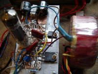
I built the differential 'top-servo' design we worked out in the schematics posted above.
DC performance was fine, better than 1mA balance. AC performance terrible, too tough to reconcile all the time constants - instability, motorboating.
Those that called for something simpler were right.
so here's the next step.
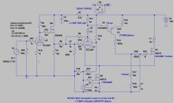
I designed it, built it and tested it today and it's much better. You need a trimmer to set up a given valve (the worst complaint), but it is very stable after that - the valve drops about 1mA when really hot, so adjust it after 10 minutes or so. dc balance to 0.5mA is quite possible, but use a 10-turn trimmer for that.
Operation:
Circuit based on a very stable current source. I bought 100pcs ZR431F a decade ago, and here's a good place to use them. It shunt regulates to 2.50V right out of the packet, and is temperature stable. Set it up with a 600V FET to give 110mA.
At cold power-ON, no current flows in either side (no crash-start blow ups!). As the valve warms up and takes current, R11 senses anode current and Q4 relays an amplified sense current to the FET M1 (antitriode).
When it is warmed up, adjust R17 to balance the currents - 55mA each in this case.
I tested it with an EL84 and EL86, in pentode mode - using a 100VA 12+12V toroidal trafo. At 250V 50mA it gave about 5W into 8.0 Ohms, and at 210V/55mA a little more.
I suspect I need a 9V trafo!
I built the differential 'top-servo' design we worked out in the schematics posted above.
DC performance was fine, better than 1mA balance. AC performance terrible, too tough to reconcile all the time constants - instability, motorboating.
Those that called for something simpler were right.
so here's the next step.
I designed it, built it and tested it today and it's much better. You need a trimmer to set up a given valve (the worst complaint), but it is very stable after that - the valve drops about 1mA when really hot, so adjust it after 10 minutes or so. dc balance to 0.5mA is quite possible, but use a 10-turn trimmer for that.
Operation:
Circuit based on a very stable current source. I bought 100pcs ZR431F a decade ago, and here's a good place to use them. It shunt regulates to 2.50V right out of the packet, and is temperature stable. Set it up with a 600V FET to give 110mA.
At cold power-ON, no current flows in either side (no crash-start blow ups!). As the valve warms up and takes current, R11 senses anode current and Q4 relays an amplified sense current to the FET M1 (antitriode).
When it is warmed up, adjust R17 to balance the currents - 55mA each in this case.
I tested it with an EL84 and EL86, in pentode mode - using a 100VA 12+12V toroidal trafo. At 250V 50mA it gave about 5W into 8.0 Ohms, and at 210V/55mA a little more.
I suspect I need a 9V trafo!
Attachments
Well done Rod,
So many times great threads like this stay at the theoretical stage of discussions that it's great to see it materialise & stable. I've been lurking on this thread since it started but have some ECL86 tubes in a Baby Huey configuration that I would love to try this design. Please report on the sound when you feel it appropriate 🙂
So many times great threads like this stay at the theoretical stage of discussions that it's great to see it materialise & stable. I've been lurking on this thread since it started but have some ECL86 tubes in a Baby Huey configuration that I would love to try this design. Please report on the sound when you feel it appropriate 🙂
Thanks - I hope you have a chance to try it out sometime. With TV valves and toroidal trafos, it should promise to be a very low cost (or junk box) build.
It's true! DIY audio should be at least as much bench time as SPICE time!
I only have a guitar preamp to hand at the moment, and that was fun, lively and natural overdrive... I'll think of some way of putting music through it when I get a minute.
The power output was the same at 40Hz as 500Hz by the way.
Hey Rod,
Nice to see you did a testrig! About the first circuit I guess a servo needs a fixed reference to work well.
For EL84 you need a tranny with ca 7V unloaded secondary voltage. They must have sweated with your 3kohm load! Circuit looks simple enough, will just try to adapt it to my depletion MOSFETS😀😀.
Last edited:
All my experience is that these circuits are remarkably forgiving of load mismatch on the output. Just goes to show how well the partial feedback works.
Underloading tends to make the bottom end suffer most.
Shoog
Underloading tends to make the bottom end suffer most.
Shoog
Hey Rod,
Did the design that was oscillating badly have a resistor in the servo tail or a CCS? I can see where a resistor there would open the door for common mode feedback oscillations.
Did the design that was oscillating badly have a resistor in the servo tail or a CCS? I can see where a resistor there would open the door for common mode feedback oscillations.
Seems like the circuit asks for a stable B+. A 5V drop upsets the currents by ca 2mA when simmed, any impressions from the real world?. Thank God its Class-A😀.
Another observation: With unequal currents through the transformer halves, clipping gets more symmetrical. Seems like it is when Ia+Is equals Id. Maybe we should add a CCS from anode to ground to equal the currents.
Another observation: With unequal currents through the transformer halves, clipping gets more symmetrical. Seems like it is when Ia+Is equals Id. Maybe we should add a CCS from anode to ground to equal the currents.
Seems like the circuit asks for a stable B+. A 5V drop upsets the currents by ca 2mA when simmed, any impressions from the real world?. Thank God its Class-A😀.
Did you try regulated G2?
Seems like the circuit asks for a stable B+. A 5V drop upsets the currents by ca 2mA when simmed, any impressions from the real world?. Thank God its Class-A😀.
Lars, that's a good one. How much better does it behave if R16 is returned to the valve cathode/FET source? Leave C1 connected to ground. Don't worry - R16 carries only 0,1mA!
Anatoliy - this error is caused by the Q4 current sense being too sensitive to supply voltage. The screen has RC filtering (or current source feed, etc according to everyone's own version!)
Hey Rod,
Did the design that was oscillating badly have a resistor in the servo tail or a CCS? I can see where a resistor there would open the door for common mode feedback oscillations.
Don, I used a cross-coupled transistor CCS (with ferrite beads in the bases).
The problem seemed to be that big signals easily overwhelmed the servo - and fixing that with filtering caused a kind of tail-chase with the antitriode FET & its filter.
I tested it with 91 Ohm sense resistors, with & without bypass caps, which did not help.
It oscillated to death in the end, and at that point I looked at it & thought there was too many parts, and it had to be simpler.
How much better does it behave if R16 is returned to the valve cathode/FET source? Leave C1 connected to ground. Don't worry - R16 carries only 0,1mA!
Had to go home and sim during my lunchhour!
Rod, had to return R16 as I have a depletion MOSFET as M1.
As Wavebourn indicated in his question the problems where gone when simming with a constant screen-voltage.
BUT..... I think we can live with some current-drift in this simple application. As long as it is within some mA. Anway 5V drop will not happen in this Class-A circuit.
Also added a CCS at the pentodes anode to ground. This to make Id=Ia+Is (41mA= 36mA+5mA)as I mentioned earlier. Now we get indications of higher power, symmetrical clipping and lower distortion!
But best simmed results so far have been achieved with a Schaded depletion MOSFET instead of the pentode........
Lars, that's very interesting!
Remember, you can use the trimmer to set the current out-of-balance.
connect a dummy load, Let the amp warm up, then add a drive signal until the amp just clips. Then adjust the trimmer until the clipping is symmetrical.
How much power can you get?
- Status
- Not open for further replies.
- Home
- Amplifiers
- Tubes / Valves
- Spud, Schade, PP, Anti-triode ECL86