Instead of 6F12P you may use 6J53P -- the same pentode in 7-pin envelope, no waste of a triode part.
Thanks for the tip Waveborn, are they easy to find on eBay?
Or as I have a bunch of 6F12Ps, one could make a less than perfect, but good enough, "gyrator" with the remaining triode to use less sand. It will anyway have an impedance of over 100k:
Or as I have a bunch of 6F12Ps, one could make a less than perfect, but good enough, "gyrator" with the remaining triode to use less sand. It will anyway have an impedance of over 100k:
An externally hosted image should be here but it was not working when we last tested it.
Sorry to be a thread jacker hear, but I am trying to simulate a circuit using LTspice and have come up with the error;
To many parameters in subcircuit type "6au6" (instance: xu3)
This is the model I am trying to use;
.SUBCKT 6AU6 A S G K
+ PARAMS: Ex=1.29250482718994 Kg1=1066.05313830636 Kp=233.038097126617 Kvb=6.26797667003452 Mu=39.2114621352395
+ Exd=0.927382241593347 Kd=1427.5732907893 Ks=2.80629495414095 Kg=0.00189539610643784
+ CCG=5.5P CPG1=.0035P CCP=5.0P
Eat at 0 Value={limit(0.636*ATAN(V(A,K)/KVB),0,1)} ; arctangent shaping
Eme me 0 VALUE={PWR(LIMIT(V(A,K),0,2000),EXD)/KD} ; diode line
Egs gs 0 VALUE= {V(S,K)/KP*LOG(1+EXP((1/MU+V(G,K)/V(S,K))*KP))} ; effective voltage
Egs2 gs2 0 VALUE={(PWR(V(gs),EX)+PWRS(V(gs),EX))/(KG1*0.636)} ; total space current
G1 A K VALUE={LIMIT(V(gs2)*V(at),0,V(me))} ; plate current
Escrn sc 0 VALUE={KS*V(gs2)*(1.1-V(at))} ; reverse arctan shaping for screen current
G2 S K VALUE={V(sc)*LIMIT(V(S,K),0,10)/10} ; screen current
G3 G K VALUE={PWR(LIMIT(V(G,K)+1,0,1E6),1.5)*(1.25-V(at))*KG} ; grid current
C1 G K {CCG} ; CATHODE-GRID 1
C2 A G {CPG1} ; GRID 1-PLATE
C3 A K {CCP} ; CATHODE-PLATE
.ENDS 6AU6
new to LTspice and people seem familaiar with the workings on this thread.
Cheers
Shoog
Edit : Just worked out the problem, I had put it in as a pentode when it was expecting a tetrode. Solved that but now its giving me
Missing Model value for subcircuit
Any ideas.
Edit : Solved that problem.
Now just need to extract a signal from the simulation.
Last edited:
Shoog:
Why use the 6AU6? But maybe you´ve got a good stock of them. They are not very linear according to the curves. Seems to be best just above 10mA. Distortion-cancellation helps but linear tubes makes it even better. Buy the 6F12P or 6J53P instead. Have checked the 6F12P in my AVO and at ca 20mA/150V/150V this one measures so nice.
Why use the 6AU6? But maybe you´ve got a good stock of them. They are not very linear according to the curves. Seems to be best just above 10mA. Distortion-cancellation helps but linear tubes makes it even better. Buy the 6F12P or 6J53P instead. Have checked the 6F12P in my AVO and at ca 20mA/150V/150V this one measures so nice.
Yes I have a stock of 6AU6's and have used them successfully in my Tabor clone and my self splitter amp. Gary Pimm uses him in his Tabor as well.
I am not going to use the 6AU6 but the tube I do intend to use is so obscure that there definately wont be a model for it. I will use the 12L8GT which is an octal dual pentode with shared screen and cathode. Even less linear I'am afraid, but I have a perverse need to build a 4 tube fully differential amp - esthetics really😛 The 6aU6 has similar operating points.
I just need to work out how to intoduce the secondary into my model now, I will look to your schematic for inspiration.
Shoog
Gary Pimm uses him in his Tabor as well.
I saw that one coming😀! I can guarantee you that mr Pimm is relying on distortion-cancellation too. So is mr Millett with his new PP. But done right to get the right overtone spectrum it is a valuable tool. This is why 2-stage amps normally work so good.
About your 12L8-GT, couldn´t you find a tube with descent Gm? Around 8mA seems to be a good starting point though.
Regarding pentode as input tube: Any screen currents are felt by cathode resistor NFB
(necessarily unbypassed for maximum plate resistance). But they do not exist as seen
by the driven load. So the impedance into the Schade network may be high, but there
is a screen current NFB error.
I remind a few posts back I showed a hybrid input stage with Triode handling the input.
And a MOSFET in cascode above the plate, to provide the high impedance. This setup
had no such screen current leakage path to mess with NFB at the cathode. Thus the
current sent into the Schade network might be more truthful to the input grid's voltage.
Hybrid cascode might also be a very practical input stage setup for a Spud.
Last edited:
I tried a bit more modelling with LTSpice, but was getting some weird voltage spiking in the Kilovolt range. Gave up.
Went back to the Tubecad article. Seems that in order to get the 12L8gt and 6as7 to play together I will need a neg rail down at about -325V, feeding a rfb resistor of 18K for 100V swing for 2.5V of input. The output impedance calculates at about 95ohms.
Sounds doable.
Shoog
Went back to the Tubecad article. Seems that in order to get the 12L8gt and 6as7 to play together I will need a neg rail down at about -325V, feeding a rfb resistor of 18K for 100V swing for 2.5V of input. The output impedance calculates at about 95ohms.
Sounds doable.
Shoog
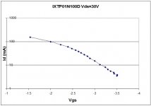
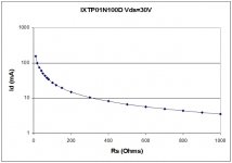
IXTP01N100D data
Here are some data which may be useful. The case temperature is about 25C (30C at higher currents), Vds about 30V, one random sample.
Looks like an excellent top-of-cascode device with low Coss, high Vgs at reasonable currents.
Vgs(off) is -2.5 min, -5V max. I haven't hooked one up on the bench yet, but from the spec it's in the ballpark of a 10M45 (which is listed as "Vg"= -5V min and operates at -2.5 or so at lower currents).
High Vgs(off) is IMO a great attribute for CCS use because it provides for higher Vds on the bottom device in a simple cascode connection (less capacitance, higher current potential).
It's the low capacitance that makes me most happylooks to me like an excellent part for cascode anode loads on driver tubes. The capacitance is about as good as the FQP150/160 parts.
My biggest wish is for IXYS to provide comprehensive device data. Supertex (IR, Hitachi, etc) all provide lengthy data sheets but IXYS information content is scant indeed. Maybe you need to have a "relationship" with them to get the test data.
Michael
Here are some data which may be useful. The case temperature is about 25C (30C at higher currents), Vds about 30V, one random sample.
Looks like an excellent top-of-cascode device with low Coss, high Vgs at reasonable currents.
Attachments
Last edited:
Regarding pentode as input tube: Any screen currents are felt by cathode resistor NFB
(necessarily unbypassed for maximum plate resistance). But they do not exist as seen
by the driven load. So the impedance into the Schade network may be high, but there
is a screen current NFB error.
I remind a few posts back I showed a hybrid input stage with Triode handling the input.
And a MOSFET in cascode above the plate, to provide the high impedance. This setup
had no such screen current leakage path to mess with NFB at the cathode. Thus the
current sent into the Schade network might be more truthful to the input grid's voltage.
Hybrid cascode might also be a very practical input stage setup for a Spud.
Another option to handle the nonlinear g2 current is to power g2 with a shunt regulator (zener, gas tube), fed by constant current, returned to the cathode.
Michael
Attachments
Regarding pentode as input tube: Any screen currents are felt by cathode resistor NFB
(necessarily unbypassed for maximum plate resistance). But they do not exist as seen
by the driven load. So the impedance into the Schade network may be high, but there
is a screen current NFB error.
Which NFB?
If I use in my Pyramid-VII and Pyramid-8 amps long tailed EL84 pentode diffpair driver, I don't see any errors.
Screen current compensated at last
I'm still away from my bench but I have been busy with this circuit still (because I like this one!!)
I warmed up LTSPICE & got the updated valve models from:
LTspice : LTspice/SwitcherCAD III
and have had fun modelling the circuit. I am really surprised how close the simulation comes to the real measurements of the one I built, so I have been encouraged to model some upgrades before building them.
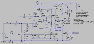
One thing I am very pleased with is the new G2-current compensation circuit. It's in the schematic as Q2-Q3-Q4. First, the screen voltage is dropped to 210V and regulated to give high performance and dc stability. Q3 senses the actual screen current, and Q4's circuit turns this from a source to a sink current. This current is then subtracted from the cathode circuit to give exact compensation. The 2 series diodes (D1, N=2) correct the offset due to the Vbes. The simulation shows the action to be almost perfect, no phase effects etc. We shall see!
The distortion is low at 6.6W output:
Harmonic Frequency Fourier Normalized Phase Normalized
Number [Hz] Component Component [degree] Phase [deg]
1 1.000e+03 1.039e+01 1.000e+00 -175.96° 0.00°
2 2.000e+03 3.404e-02 3.277e-03 90.52° 266.48°
3 3.000e+03 1.002e-01 9.650e-03 -168.10° 7.86°
4 4.000e+03 1.064e-02 1.024e-03 111.17° 287.13°
5 5.000e+03 1.437e-02 1.384e-03 18.98° 194.94°
6 6.000e+03 2.055e-03 1.978e-04 -62.13° 113.83°
7 7.000e+03 1.587e-03 1.527e-04 -154.16° 21.80°
8 8.000e+03 2.704e-05 2.603e-06 19.28° 195.24°
9 9.000e+03 6.808e-05 6.554e-06 -100.25° 75.71°
Total Harmonic Distortion: 1.033839% Pout=6.6W
Distortion rises to about 4% (dominated by 3rd) at 9W output, which doesn't seem bad for an EL84 and only 240V supply.
Lars, for your transformer model 25H to 0.1H was that 6V type? Do you assume it's 7V unloaded?
I'm still away from my bench but I have been busy with this circuit still (because I like this one!!)
I warmed up LTSPICE & got the updated valve models from:
LTspice : LTspice/SwitcherCAD III
and have had fun modelling the circuit. I am really surprised how close the simulation comes to the real measurements of the one I built, so I have been encouraged to model some upgrades before building them.
One thing I am very pleased with is the new G2-current compensation circuit. It's in the schematic as Q2-Q3-Q4. First, the screen voltage is dropped to 210V and regulated to give high performance and dc stability. Q3 senses the actual screen current, and Q4's circuit turns this from a source to a sink current. This current is then subtracted from the cathode circuit to give exact compensation. The 2 series diodes (D1, N=2) correct the offset due to the Vbes. The simulation shows the action to be almost perfect, no phase effects etc. We shall see!
The distortion is low at 6.6W output:
Harmonic Frequency Fourier Normalized Phase Normalized
Number [Hz] Component Component [degree] Phase [deg]
1 1.000e+03 1.039e+01 1.000e+00 -175.96° 0.00°
2 2.000e+03 3.404e-02 3.277e-03 90.52° 266.48°
3 3.000e+03 1.002e-01 9.650e-03 -168.10° 7.86°
4 4.000e+03 1.064e-02 1.024e-03 111.17° 287.13°
5 5.000e+03 1.437e-02 1.384e-03 18.98° 194.94°
6 6.000e+03 2.055e-03 1.978e-04 -62.13° 113.83°
7 7.000e+03 1.587e-03 1.527e-04 -154.16° 21.80°
8 8.000e+03 2.704e-05 2.603e-06 19.28° 195.24°
9 9.000e+03 6.808e-05 6.554e-06 -100.25° 75.71°
Total Harmonic Distortion: 1.033839% Pout=6.6W
Distortion rises to about 4% (dominated by 3rd) at 9W output, which doesn't seem bad for an EL84 and only 240V supply.
Lars, for your transformer model 25H to 0.1H was that 6V type? Do you assume it's 7V unloaded?
For comparison, with the Schade network disconnected, the distortion at 6.7W is upped to 4.8%:
Harmonic Frequency Fourier Normalized Phase Normalized
Number [Hz] Component Component [degree] Phase [deg]
1 1.000e+03 1.093e+01 1.000e+00 -179.46° 0.00°
2 2.000e+03 1.397e-01 1.278e-02 80.85° 260.31°
3 3.000e+03 4.962e-01 4.541e-02 -179.06° 0.41°
4 4.000e+03 7.481e-02 6.846e-03 91.77° 271.23°
5 5.000e+03 1.960e-02 1.793e-03 0.84° 180.30°
6 6.000e+03 3.852e-03 3.525e-04 97.98° 277.45°
7 7.000e+03 6.223e-03 5.694e-04 3.02° 182.48°
8 8.000e+03 2.900e-03 2.654e-04 -87.69° 91.77°
9 9.000e+03 1.139e-03 1.042e-04 179.83° 359.29°
Total Harmonic Distortion: 4.770777% 6.76Wout
Hey Rod,
The 25+25:0,1H is just an imaginary transformer with 8000:8ohm. A 6V toroid with 6,8V unloaded would be 25+25:0,08H and close to 9000:8ohm.
The 25+25:0,1H is just an imaginary transformer with 8000:8ohm. A 6V toroid with 6,8V unloaded would be 25+25:0,08H and close to 9000:8ohm.
Rod's new approach or the earlier mentioned simple screen shunt regulator approach both remove the screen current issue from the OT DC balance. But as Ken was pointing out I think, the plate current is distorted by the removal of the non-linear screen current to some extent. Returning the screen current to the plate current might be a better approach.
A cap between Q2 collector and U2 plate would do this. (no need for Q3,Q4 then but Q2 needs to be HV part) R15 would need to be an inductor to a slightly higher B+ to allow for the plate voltage to dip below the regulated screen voltage. Likely some other ways too. Maybe just connect Q2 collector to a UL tap on the OT.
Hmm.., the collector to UL tap approach might fix another problem too. As Michael pointed out some time ago, the "triode" side dynamically unbalances the OT DC balance at high signal level due to distortion components (3/2 power current growth for loaded triode, 2nd harmonic mainly). With the UL tap, the "plate" current effectively starts using less xfmr winding turns as the screen current component increases at large signal.
Don
Last edited:
Rod's new approach or the earlier mentioned simple screen shunt regulator approach both remove the screen current issue from the OT DC balance. But as Ken was pointing out I think, the plate current is distorted by the removal of the non-linear screen current to some extent. Returning the screen current to the plate current might be a better approach.
Don,
In all the top-sensed versions of the circuit, the dc balance in the trafo is independent of screen current, as it's not measured.
The new circuit attempts to sense the value of dynamic screen current, which does not flow in the valve side of the trafo, but if uncompensated, would flow in the MOS side. By taking an equal current out at the cathode, the aim is to have an exact mirror of the anode current flowing in the MOS side (unless I'm missing something)!
If the simulation is anywhere near right (it's been doing well up to now!) there's only about 1% distortion at 6.6W (see data above - demonstrating the value of the Schade network)). Even if that translates into 1% dc imbalance (about 0.5mA) I think we'll still have room to move in a toroid... may be best to set the dc balance trimmer while the amp is working at rated power though... adjust for best bass handling or symmetrical clipping perhaps.Hmm.., the collector to UL tap approach might fix another problem too. As Michael pointed out some time ago, the "triode" side dynamically unbalances the OT DC balance at high signal level due to distortion components (3/2 power current growth for loaded triode, 2nd harmonic mainly). With the UL tap, the "plate" current effectively starts using less xfmr winding turns as the screen current component increases at large signal.
Hey Rod,
This amp has moved a little to far from the original, simple approach😉. I have designed a new driver, with a common pentode and some sand, that takes use of distortion-cancellation to match the EL84.
Have also found another way to compensate for distortion between driver and output device.
Will start a new thread later today where we can develop it further.
Do you have a *.asc of the screen-compensation version?
Lars, It's a little less simple, but the added parts are all easy and low cost. It's also low voltage & mostly protects itself from many possible fault conditions. And it appears to offer very high performance for such a cheap build.
OK, it may wind up needing a PCB, but I'll be happy to do that.
Here's the LTspice schematic. If you use the TL431 (& I recommend it!) the TL431A model (Hartmut's) is far more appropriate for dynamic conditions than the other models (TI and IEEE).
I have a driver in mind for this too, with very high performance! Be fun to compare.
Rod
Attachments
- Status
- Not open for further replies.
- Home
- Amplifiers
- Tubes / Valves
- Spud, Schade, PP, Anti-triode ECL86