Thanx for all your hard work Brian.
Maybe David changed this purely for cosmetic reasons and he would change it back ?
Maybe David changed this purely for cosmetic reasons and he would change it back ?
Hi.
Has anyone succesfully used Brians sheets in the online google-sheets?
I can open the sheet, but the box-drawings are very messed up. I assume that its some setting on what kind of graph is being used.
Also the "optimize, import, ect" buttons are not there, but I assume thats because google sheets do not support macros?
Kind regards TroelsM
I've seen this particular layout from time to time while browsing around the Internet. Would anyone be interested in a BOXPLAN for it? Seems like a curious mix between vented and TL. The 45 degree "braces" in some of the corners are a bit superfluous, so I might leave them out of the schematic ...

Yes please, I'd like to play around with models of it - have seen similar boxes referred to as "mini scoops", and would be interested to sim them with a considered approachWould anyone be interested in a BOXPLAN for it? Seems like a curious mix between vented and TL.
Good point. It's close - the expansion changes in the first and last segments. I think I'll just modify BOXPLAN-TL1 to allow different segment expansions rather than just model a "straight" TL. That way it can be used to model both types of designs.Brian isn't it practically the same as the Boxplan TL1?
I managed to put together something, but I'm not sure if I'll develop it any further. I suspect that the actual Fb might be slightly higher than predicted due to trying to describe the entire design with four segments with two discrete steps:

Resulting model:

The predicted response looks like this:

A properly-designed ODTL would provide a much smoother response between Fb and 200 Hz, but slightly less gain across the passband.
I probably wouldn't build this.
Resulting model:
The predicted response looks like this:
A properly-designed ODTL would provide a much smoother response between Fb and 200 Hz, but slightly less gain across the passband.
I probably wouldn't build this.
I suspect that the actual Fb might be slightly higher than predicted due to trying to describe the entire design with four segments with two discrete steps
Possible alternative model which would enable the port tube / transmission line to be described using up to five segments (throat adaptor included). The driver is inline rather than being offset but the difference in results should not be significant - the fundamental frequency remains the same. The default driver has been used in the two test examples, with the black trace on the comparison chart showing the alternative model results.
Original offset driver model:
Alternative inline driver model:
Alternative inline driver model:
Results comparison:
That is an interesting alternative approach. It should allow for better description of the S1-S5 path too. However, I don't think I'm going to do much more development of this project, as that 100 Hz - 200 Hz response is pretty horrible.
The frequency response looks quite normal for a transmission line, in which the speaker has a very small offset and the tunnel itself has an almost constant cross section.
Who cares!! Is a sub!! Put an HP @80hz LR24 or 48....bam!! Ugly signalas that 100 Hz - 200 Hz response is pretty horrible.
.gone!!!
You're still going to have problems through the x-over region, and IMO brick-wall filters on subs makes them sound ... not good.
Why settle for this when there are better designs available?
Why settle for this when there are better designs available?
Who cares!! Is a sub!! Put an HP @80hz LR24 or 48....bam!! Ugly signal
.gone!!!
You are wrong…. But unless you actually listened to some of these things and fixed all that junk acoustically with an offset driver entry and change in the resonator shape (or instead with a Peq dsp ) instead of just slapping a generic XO on it I don’t doubt you would just assume otherwise.
I think I’ve sent you recordings of REALLY bad versions of this (some paraflex or roar experiments ringing) in the past?
You can fix all that junk with a bit of effort and fine tuning of the design
Attachments
Last edited:
Hmm, might have to eat my words here, ok, some of them ...
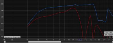
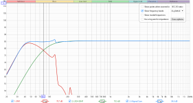
Here's a sim of the BOXPLAN mini-scoop loaded with a B&C 15BG100 LP'd @ 80 Hz LR 24dB/octave, combined with a theoretical speaker HP LR 24dB/octave at the same frequency. With a little time-delay on the top, the overall response is pretty flat.
No, I said "some" of my words, because it seems a bit "wasteful" to LP a 40 Hz bass bin @ 80 Hz. 40~100 would be the minimum I'd aim for.

The next step now is to "validate" the sim. But I really don't want to build one of these - I need to find someone who's done so to see if the sim does a good job of predicting its impedance curve and frequency response.
Here's a sim of the BOXPLAN mini-scoop loaded with a B&C 15BG100 LP'd @ 80 Hz LR 24dB/octave, combined with a theoretical speaker HP LR 24dB/octave at the same frequency. With a little time-delay on the top, the overall response is pretty flat.
No, I said "some" of my words, because it seems a bit "wasteful" to LP a 40 Hz bass bin @ 80 Hz. 40~100 would be the minimum I'd aim for.
The next step now is to "validate" the sim. But I really don't want to build one of these - I need to find someone who's done so to see if the sim does a good job of predicting its impedance curve and frequency response.
Attachments
Hi Brian,
I am trying to model one of GM's MLTL ( https://www.diyaudio.com/community/threads/mltl-cabinet-for-416-8b.113177/ ) using Boxplan-MLTL3. The external dimensions of the cabinet are H = 106.66 cm, W = 76.2 cm, D = 51.435 cm, with a divider placed mid point between the front and rear panel. I am not able to get the internal divider panel (Panel F) to be placed correctly. My thought was that increasing the Box Parameters Depth (External), Panel F will be placed correctly. That obviously is not the case. How does one specify "x" for Panel F? Also the panel dimensions seem incorrect or I am missing something? I did increase the graph axis max value.
Simmonds
Oops, missed changing the hornresp params in the general instructions. Will try and that and see.
Simmonds
Simmonds
That design is an offset-driver / offset-vent MLTL. I don't think BOXPLAN-MLTL3 can be used to model it.
- Home
- Loudspeakers
- Subwoofers
- Spreadsheet for Folded Horn Layouts...