One of the few times that I saw a design limited by power and not excursion , 95% of my sims hit Xmax before Pmax 😎.
That happens with budget drivers.
That happens with budget drivers.
I've seen plenty of car audio drivers take multiple times their rated power in SPL tests.
I wouldn't play that driver at a constant 138 volts. But, a quick burst every now and then MIGHT not k!ll it.
I wouldn't play that driver at a constant 138 volts. But, a quick burst every now and then MIGHT not k!ll it.
Considering the Dayton Audio HTS545HE-4's power rating, 88volts (rather than 138 volts) should probably be considered it's maximum.
Side note here:
Sometimes the power rating from amplifier is different from drivers, mainly when talking about class D ones.
If I'm remembering well, the drivers are tested with sine waves, so the 88volts Art mention is the average voltage and so the peak should be 88*sqrt(2)= 124volts.
Class D amplifiers are being tested with burst signal, and in general they are rated according to the peak voltage and so peak power. The ability for this amplifier sustain low frequencies may vary because the average power of the amplifier is unknown, so there are some brands that people say that can't sustain voltage for bass reproduction properly.
Some class AB amplifiers are still tested with different signals and sometimes their power rating are related to the average voltage and average power, so the user needs to investigate what is the peak power for the amplifier. In general is sine wave signal and so peak power/voltage is the averate x sqrt(2).
A good approach would by matching the peak power of the driver with the peak power of the amplifier. In the real world you will need to compromise one of the two and rely on protections.
Probably when looking to Hornresp max diaphragm displacement that information will be related to peak voltage/power.
The 426-B test uses band limited pink noise with a crest factor of 6dB with an RMS voltage equivalent to the rated power, in other words, a 4 ohm nominal driver with a 2000 watt rating uses 89.44 volts for the test.If I'm remembering well, the drivers are tested with sine waves, so the 88volts Art mention is the average voltage and so the peak should be 88*sqrt(2)= 124volts.
The Hornresp diaphragm displacement is based on the voltage specified, which includes the x1.41 peak.Probably when looking to Hornresp max diaphragm displacement that information will be related to peak voltage/power.
For a few seconds when the driver starts out cool, no problem.I've seen plenty of car audio drivers take multiple times their rated power in SPL tests.
If that driver was limited to ~63v RMS long term, (~ 2000 milliseconds) it might survive a few milliseconds of 138v (194.58v peak, ~10,000 watts).I wouldn't play that driver at a constant 138 volts. But, a quick burst every now and then MIGHT not k!ll it.
I would not recommend more than 124v peak limiting with the TH impedance curve.
The 426-B test uses band limited pink noise with a crest factor of 6dB with an RMS voltage equivalent to the rated power, in other words, a 4 ohm nominal driver with a 2000 watt rating uses 89.44 volts for the test.
There are so many standard to remember that for an enthusiast like me is hard to remember. For the standard 426-B you are right, but curiously check attached table.
Probably if the driver that is intended to be used at higher frequencies, so a HPF could be applied at 20Hz or 40Hz, the crest factor of tested signal vary leading to a room to increase peak power / voltage while reproducing music signal.
For me, audio is really hard sometimes. Too many variables to manage 🙂
Attachments
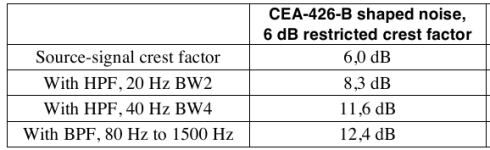
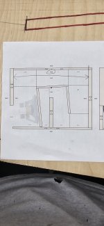
For the math to line up I think this number has to be 38 unless Ive drawn something wrong or done something out of wack which then makes external dimensions 39.5....also where the sub mounts has to be 1.5 they weigh 116 pounds
The extra length doesn't matter they aren't having to fit in anywhere or crunch on space I need them to get low is all I care about really id like to be able to get down to 26 or 27 before it drops off but the more I mess with my head just spins lol 😂
The extra length doesn't matter they aren't having to fit in anywhere or crunch on space I need them to get low is all I care about really id like to be able to get down to 26 or 27 before it drops off but the more I mess with my head just spins lol 😂
Attachments
Last edited:
One of the best things about Brian's spreadsheets is that the layouts make for very easy and precise construction. I think you've missed something if you're having to resort to manually drawing your build?

36.5in internal depth + 1.5in (front and back panels) = 38in external depth.For the math to line up I think this number has to be 38 unless Ive drawn something wrong or done something out of wack which then makes external dimensions 39.5....also where the sub mounts has to be 1.5 they weigh 116 pounds
The extra length doesn't matter they aren't having to fit in anywhere or crunch on space I need them to get low is all I care about really id like to be able to get down to 26 or 27 before it drops off but the more I mess with my head just spins lol 😂
That's where bracing comes into play.
Since your enclosure is 21.75in wide internal, use 2 braces instead of my 1.
Originally, he tried to fit a 21.5in wide driver frame on a 20.94in panel.One of the best things about Brian's spreadsheets is that the layouts make for very easy and precise construction. I think you've missed something if you're having to resort to manually drawing your build?
I think his L12 is too long for a MTH (double fold) style enclosure that is 36.5in high by 36.5in deep internally.
To use a longer L12 that is more than half the diameter of a 21.45in driver, he would have to use a Keystone type fold and alter his 38in high x 38in depth external dimensions.
this was my dats in the end after the final build. I havent gotten to listen to any music through it yet but from the dats to my knowledge it looks like its going to be pretty decent.

this was the hornresp prediction. You want the first 2 humps to be the exact same height though dont you? if so then looks like my build came out better than predicted?
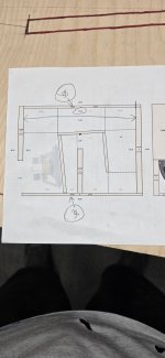
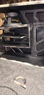
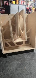
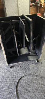
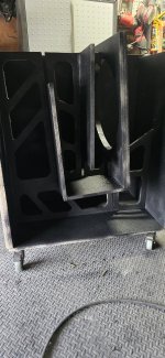
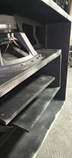
here are some build pics i havent finished the outside yet but only 3 more to build lol going to do some more testing before i build them but I think i am going to be pretty pleased.
this was the hornresp prediction. You want the first 2 humps to be the exact same height though dont you? if so then looks like my build came out better than predicted?
here are some build pics i havent finished the outside yet but only 3 more to build lol going to do some more testing before i build them but I think i am going to be pretty pleased.
Attachments
There's no requirement for the peaks to be at the same height.
Export both measurements as FRD files and import them into REW. There you can compare them directly to see how close the build came to the sim. If you're very close, the frequencies at which the upper two peaks and the two dips should be very close matches to those predicted by the sim. The last peak might be in approximately the same location, and quite likely much lower than predicted.
Export both measurements as FRD files and import them into REW. There you can compare them directly to see how close the build came to the sim. If you're very close, the frequencies at which the upper two peaks and the two dips should be very close matches to those predicted by the sim. The last peak might be in approximately the same location, and quite likely much lower than predicted.
Well done with the bracing. I think that bracing is critical as the energy your build will generate will be immense!
the purple is hornresp and the green is my dats. to be honest im not sure how close of an exact match is considered acceptable or what the difference between mine and the sims means when relating the 2. Is it better to have more distance betweenb the first 2 humps or for them to be closer? from what i understand i guess it really doesnt matter that will be determined by driver parameters? and as far as frequncy response is this showing me a better or worse response? or does this have no relation? ill know after take the measurement obviously, i just like to ask the questions idk
What about a freq sweep and see it against the sim.
But if I'm not wrong the sim Fb is around 37.5 and your data around 33... So means the tuning of the box is lower than predicted , nice!!
What was your choice of driver ? I lost track of this thread
, kraken?
So you end up using the MTH type of fold ? Or the keystone ?
And btw , why you don't start a thread to document your build.
Last edited:
- Home
- Loudspeakers
- Subwoofers
- Spreadsheet for Folded Horn Layouts...