Would you be able to update the boxplan Poc7 or Cubo to 64 bit whenever you have a second? I think Cubo is going to work good for what I need my next build to be.
Sorted. I just uploaded updated versions of those workbooks that deal with that specific issue.
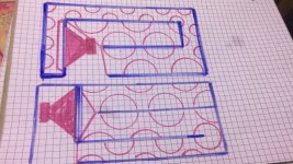
Anyway to get tl1 updated as well whenevr you get a second? Also when dealing with the enclosure in mltl 3, do I need to increase manufacture recommended port area by a certain amount for transmission line style boxes? I just got done building 1 and the recommended port area is 60 square inches for the 2 woofers I used. I gave it 76 but I am still getting chuffing. I didn’t know if this was common with transmission line boxes or if there was a rule to know on how much port area to have etc.
Also was wondering about the filling feature in hornresp, when I choose to add filling and raise the number what exactly is that number rated in? Or how does that translate into what you actually fill with?
Also was wondering about the filling feature in hornresp, when I choose to add filling and raise the number what exactly is that number rated in? Or how does that translate into what you actually fill with?
I'm on vacation at the moment, so I've got a bit of time to update my website. I'll have a look at the BOXPLAN-TL1 workbook.
Concerning your question re BOXPLAN-MLTL3, the answer really depends on what you're trying to build. For subwoofer duty, I recommend starting with a vent area that's at least 1/3rd the combined Sd of the woofers. For full range speakers, vent area may need to be lower because the larger the vent area, the more likely audible out of band resonances will be produced through the vent. The BOXPLAN-MLTL3 layout is more suitable for full-range TLs rather than subwoofer TLs.
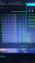
Concerning the filling, Hornresp provides a rough idea of what adding filling will do to the box. The way I use it is to look at what the impedance curve looks like at the amount of filling that I need to add to get the target response in Hornresp that I'm tryin to achieve. Then, when you build, keep adding filling until the impedance curve's minimum points line up with those given in the Hornresp sim.
Concerning your question re BOXPLAN-MLTL3, the answer really depends on what you're trying to build. For subwoofer duty, I recommend starting with a vent area that's at least 1/3rd the combined Sd of the woofers. For full range speakers, vent area may need to be lower because the larger the vent area, the more likely audible out of band resonances will be produced through the vent. The BOXPLAN-MLTL3 layout is more suitable for full-range TLs rather than subwoofer TLs.
Concerning the filling, Hornresp provides a rough idea of what adding filling will do to the box. The way I use it is to look at what the impedance curve looks like at the amount of filling that I need to add to get the target response in Hornresp that I'm tryin to achieve. Then, when you build, keep adding filling until the impedance curve's minimum points line up with those given in the Hornresp sim.
Done.Anyway to get tl1 updated as well whenevr you get a second?
Hello Brian,
What is the best spreadsheet to take advantage of hornresp's new Transmission Line design tool?
What is the best spreadsheet to take advantage of hornresp's new Transmission Line design tool?
The ones that allow for a significant offset of the driver from the closed end of the line would probably be the best ones. At least one of them is already configured to use my equation as a starting point for a TL (BOXPLAN-TL2).
MLMTL3 can accommodate the area taper ratio, looks like but there looks no straightforward way to do that.The ones that allow for a significant offset of the driver from the closed end of the line would probably be the best ones. At least one of them is already configured to use my equation as a starting point for a TL (BOXPLAN-TL2).
giri, observe the 3:1 non taper format it suits a more obvious result in some drivers Aand a taper is a mess in reality if liking at 300/100/60cm for exampleMLMTL3 can accommodate the area taper ratio, looks like but there looks no straightforward way to do that.
odd harmonics that can fall into place if you look at radians vs degrees vs centimeters in the numbers required to use 300 in an offset driver (300x 0.3490658) is 104.72(60 degrees) btw
these sonething wrong with ‘taper’ and trying to explain it(its not akways true especially in a full range odmltl) is pointless. experience it is the only arguement
Attachments
There are several good reasons reason to taper a TL. For example a straight TL for a given driver might have enough CSA at the driver installation point to actually install the driver if its motor structure is large. Tapering it will provide a larger CSA at the driver installation point. Tapering is also a good way to move the next null in the response (caused by the driver and vent response being out of phase) high enough in frequency so it's outside of the desired passband and perhaps even high enough to be more effectively dealt with using lining or stuffing in the TL.

you cant even look at a suggestion your so arrogant …. im sorry , i give up . youre not taking any feedback from potential users or former(the ones who asked elsewhere for help)There are several good reasons reason to taper a TL. For example a straight TL for a given driver might have enough CSA at the driver installation point to actually install the driver if its motor structure is large. Tapering it will provide a larger CSA at the driver installation point. Tapering is also a good way to move the next null in the response (caused by the driver and vent response being out of phase) high enough in frequency so it's outside of the desired passband and perhaps even high enough to be more effectively dealt with using lining or stuffing in the TL.
because you gave them none..
If that's true, then thanks!im sorry , i give up .
i love you (on sunday’s) 😝😝Ooh, I just realised that the forum has an ignore option... 🙂
or this (use a very small rear chamber to enforce the same concept ) you get similar consistent results and supports the exact 104.72/195.28 called for i terstingly( look at 12 on 6.9375 to understand and why and see the 104.72 cm to radians to this 300 cm model?let’s dissect things starting with these?
akward, but the exploit things a bit like this driver can too? recognize how very seriously i alugn the fill on the 3 x1/4 harmonic issue… (no path means a concentric corner loaded subwoofer essentially) …
0.3490658 is pi/9 (martin fails to understand this btw) or all
if these i relation to a pendulum swing in 1 second at 1 meters length… (wikipedia barely touches on this as its all
been diluted with the 2017 speed of light change in definition for sheep )
if you’ve ever calibrated instruments as a nuclear power plant operation/radcon tech with cesium 133-136 or similar, you understand this and the speed of light very much as you will when reading staff dosimeter (with crystals) …
Attachments
Last edited:
There are several good reasons reason to taper a TL. For example a straight TL for a given driver might have enough CSA at the driver installation point to actually install the driver if its motor structure is large. Tapering it will provide a larger CSA at the driver installation point. Tapering is also a good way to move the next null in the response (caused by the driver and vent response being out of phase) high enough in frequency so it's outside of the desired passband and perhaps even high enough to be more effectively dealt with using lining or stuffing in the TL.
Negative taper gets you small and low.
Positive taper gets you big and loud.
Loud, low, small....pick 2.
try a reduction at the second green line not a taperNegative taper gets you small and low.
Positive taper gets you big and loud.
Loud, low,
Attachments
For TLs, the volume required for a particular driver tends to remain approximately the same for a given F3 and Fb. All you're really changing by adjusting the length of the TL is where all the harmonics end up. The shorter the TL, the higher in frequency the harmonics end up. That's why my current process for designing TLs starts with identifying the best volume for the TL, and then working out what's the best length for it based on what I want the bandwidth to look like.A negative taper segment volume can equal a reduced straight segment volume.
- Home
- Loudspeakers
- Subwoofers
- Spreadsheet for Folded Horn Layouts...